Hello Amienois et les autres,
The reason the double c were used as output is great bandwith. BUT you dont want that with the power transformer because all the noises from the powerline will go through it.
The R core from Selectronic is the one that Jean Hiraga uses in his dac supply has a static screen to stop noises going from primary to secundary.
If you use EI the air gap( entrefer) is the place where the magnetic radiation is the strongest.
YES i will resist because i have some other porjects running. New tube pre amp with battery power supply ( gary Dodd) and i wanna get another tripath amp which will have battery supply too. The pre amp is still under construction in the USA. The amp have some questions that need to be answered but i think it will be here end July.
Sincere greetings, Edward
So, I understand that typically OSCON type caps are better for digital circuits and something like a Silmic or Panasonic FC are better for analog circuits, but we're not talking about caps directly for those circuits are we? We're talking about caps for the regulators. So according to Guido's recommendations, we should be ideally using OSCON caps just before any shunt regulator.
Or is it not that simple?
Hi James,
I think you know the answer yourself if I reed between the lines. No, it is not that simple, although a shunt reg. Has a pretty good isolation you can still hear what kind of capacitor is in front of it.
Doede is right, capacitors often make subtle differences, this is nice for soundtuning in your own system. The oscon, panasonic and silmic are good choices. I find the muse too dark sounding for my set. Somebody else might like them in a light sounding system.
@Edward,
The raw voltage for the shunts is not very critical, you can use 10-12v for the 8v shunts so there is no need for using different transformers.
@John,
1) tent shunts and balanced out.
2) yes you can if you run unbalanced. But I think you will prefer balanced out. Even if your amp is single ended (mine is also).
Regards,
Last edited:
I’ve been playing around with different Cap sizes in the place of the 4700uf's, in the standard DDDAC regulated power supply.
I tried 2x 6800uf, which gave a fuller body in the lowest bass section, but made the bass quit muddy/less defined.
Then I tried 2x2200uf which gave greater detail in the higher bass tones but also made the bass thinner and less deep.
So I settled for one of each.
The question I have is:
I’m now working out a new unregulated supply and most of you seem to be going for 2200uf caps. What’s the reason behind this? The value of 2200uf doesn’t seem quit big enough and why use three of the same values in series (in a CLCLC arrangment) where there could also be different values that would augment each other?
Last edited:
Thanks 🙂 that makes sense, I just wanted to double check 🙂 I will install some header sockets and try a few things and see what I prefer.Hi James,
I think you know the answer yourself if I reed between the lines. No, it is not that simple, although a shunt reg. Has a pretty good isolation you can still hear what kind of capacitor is in front of it.
Doede is right, capacitors often make subtle differences, this is nice for soundtuning in your own system. The oscon, panasonic and silmic are good choices. I find the muse too dark sounding for my set. Somebody else might like them in a light sounding system.
,
Very helpful. Thanks Doede 🙂In regard to caps, nothing is easy unfortunately.... my experience ist that it can be pretty personal what caps you like..... also depending on how it fits into the sound of the rest of your chain. I would not say my choice for the Nichicons was totally arbitrary, but also I wanted to have a good cap at an affordable price and also with good availability. That is why I picked them. I still believe they are pretty good. The best in existence? Probably not. at least a point of discussion and experience I guess.... And from that point the tweaking can start if you like. just stating this cap or that cap is the best works for own results but might be a mal advise for some one else.... but keep sharing experience, it always helps finding starting points for further experiments 🙂
I've copied Stefan's original plan and used 2,200uf in pairs to give 4,400uf for each 'C' stage.The question I have is:
I’m now working out a new unregulated supply and most of you seem to be going for 2200uf caps. What’s the reason behind this? The value of 2200uf doesn’t seem quit big enough and why use three of the same values in series (in a CLCLC arrangment) where there could also be different values that would augment each other?
I read somewhere that having all stages the same size was not necessarily the best, so was going to experiment with changing one of the stages a little and see if there's a difference I can measure and hear.
I noticed Stefan has changed his first stage to 3 x 2,200uf silmics now
I have tried this myself sometime ago and concur. I ended up using 2x4700uf but with Mundorf M-Lytic AG. I thought with higher value uf, the sound were fuller but The speed for bottom ends were a little sluggish.I’ve been playing around with different Cap sizes in the place of the 4700uf's, in the standard DDDAC regulated power supply.
I tried 2x 6800uf, which gave a fuller body in the lowest bass section, but made the bass quit muddy/less defined.
Then I tried 2x2200uf which gave greater detail in the higher bass tones but also made the bass thinner and less deep.
So I settled for one of each.
Btw, abit out of topic here but for those are waiting for BBB Cape to I2S to DDDAC like myself, there is new development. Apparently the cape is done and await for minor tuning. Sounds like I might abandoned my Pi isolator(Acko S03) soon. 😀
Cheers,
Chanh
I've copied Stefan's original plan and used 2,200uf in pairs to give 4,400uf for each 'C' stage.
I read somewhere that having all stages the same size was not necessarily the best, so was going to experiment with changing one of the stages a little and see if there's a difference I can measure and hear.
I noticed Stefan has changed his first stage to 3 x 2,200uf silmics now
Hi James&Chanh,
I'm particularly interested in changing the value, not so much the number off. My line of thinking (very much inspired by Stefan’s and Cees their inputs) is that, by adding the same type, the power of that caps signature will be increased, but the signature will stay the same. By adding different values the signatures will complement each other. Also bigger caps will have a bigger ripple, so cascading values down, will deal with this better.
What I’m currently thinking is a cascaded approach, something like:
PS (CLCLC design): 2x 3300uf 50V Silmic II (first C), 2x 2200uf 25V Silmic II (sec C), 2x 1000uf 25V Silmic (third C)
DDDAC mainboard: 470uf Silmic II 25V
DDDAC DAC board (leaving original regulators): 200uf Silmic II (instead of row of 4 Muse 47uf’s), 100uf Silmic II Last cap before 8v and 3.3v regulators), all remaining caps OSCON’s 47uf 16v (after regulators)
What do you guys think?
Sounds like a good idea to me. I would imagine with the extra load from your dac, it will be close to 12v now
Yes, thanks.
The reason the double c were used as output is great bandwith. BUT you dont want that with the power transformer because all the noises from the powerline will go through it.
That's right, haven't thought about that. I'll rethink that later.
Right now the circuit is assembled.
An externally hosted image should be here but it was not working when we last tested it.
Very early impressions : analog shock. Every adjective Stefan used is relevant. But I need some hours of listening to comment furthermore.
Anyway, the HF noise I had is now almost gone (for the best).
Hi James&Chanh,
PS (CLCLC design): 2x 3300uf 50V Silmic II (first C), 2x 2200uf 25V Silmic II (sec C), 2x 1000uf 25V Silmic (third C)
DDDAC mainboard: 470uf Silmic II 25V
DDDAC DAC board (leaving original regulators): 200uf Silmic II (instead of row of 4 Muse 47uf’s), 100uf Silmic II Last cap before 8v and 3.3v regulators), all remaining caps OSCON’s 47uf 16v (after regulators)
What do you guys think?
Sounds like a good idea. Anybody knows if there is a theorical advantage to add bypass caps here ?
I'm wondering why you want to leave original regulators. Don't forget such a PSU is raw and just smoothed out. High end regs are a giant step here in general, even more with an unregulated PSU !
Last edited:
...
I'm wondering why you want to leave original regulators.
Because, I want to take it one step at a time, to be able to tell/hear what's what first, play around with the caps a little bit (& I'm not realy in a hurry anyway)
Looking at your picture. What's your voltage after the first caps and what bleeder value are you using?
Last edited:
here's a quick few graphs from my scope.
Just some very quick experiments with differing values for the first capacitor stage of the CLCLC power supply. 2nd and 3rd C are each 2 x 2,200uf Panasonic FM
For the graphs: Blue is input to the 1st choke, Brown is output of the first choke, Green is output of the second choke and Red is taken at the input of the 8v regulator on the DAC board.
First with no cap

then a small 1uf film cap

1.8uf Russian Teflon


Just some very quick experiments with differing values for the first capacitor stage of the CLCLC power supply. 2nd and 3rd C are each 2 x 2,200uf Panasonic FM
For the graphs: Blue is input to the 1st choke, Brown is output of the first choke, Green is output of the second choke and Red is taken at the input of the 8v regulator on the DAC board.
First with no cap
then a small 1uf film cap
1.8uf Russian Teflon
here's a quick few graphs from my scope.
That's very cool. I wonder what a 2200uf or 3300uf input cap would look like, probably better still..
better in terms of smoother output and much less work for the first choke to do, yes, I'd be fairly sure of that, but with this particular transformer, it makes the ultimate output too high for me.That's very cool. I wonder what a 2200uf or 3300uf input cap would look like, probably better still..
I have a spare toroidal, I'll try removing some of the secondary windings and see if I can get it where I need it to be.
Now I have this scope set up, I can have a play when I find the time and see and measure the results
Hello,
I do remember a french power amp design ( nemesis compense) that did use a toriodal power transformer as an output transformer. One secundary winding was used to let a current flow and the other winding was for the signal. Like a push pull tube amp.
So no toriodal for power supply i guesss lol.
Nice graphs but need experts to judge which will give the best sound.
A bigger cap will generate more negative effects from the chsrging currentssincere greetings, edward
Hello,
Was a bit distracted when typing this morning.
The transformer used was a toriodal one. 2*110 volts primary side and secondary 2*40volts.
One primary winding carries the signal the other carries a current with high impedance and one secundary winding is used for the output. With 10 watt power the minus 2 db point was at 10 to the fifth power. In the the article Jean Hiraga did really like this amp. Maybe a reason he didnt pick a toriodal transformer but an R-core with a static shield for hid DDDAC power supply?
Sincere greetings, Edward
Just realised I have a 2 x 9v Transformer spare from my dddac 5v power supply 🙂 I might see if that works out any closer to 12v with my chokes and a cap input.
today's adventures in making a choke power supply, I've gone back to the start and using my scope to find the configuration and values that measure well. For reference, I'm using a very cheap and basic USB scope, but it seems it's good enough to show me what I need.
All I have connected up so far is the transformer, shottkeys, caps for the first 'C', the first choke and a 24ohm bleed resistor after the choke to provide approx 0.5A load.
So first up, how large should the first C stage be?
I have some 2,200uf and 1,200uf Panasonic FM caps, so I tried a few different combinations to see what the smallest value I could use that gave good smoothing.
In these graphs, Blue is before the first choke, Brown is after.


It looks to me like there's almost no difference between 5,600uf and 6,600uf. So I'll stick with 5,600uf (2 x 2,200uf and 1 x 1,200uf) for the first C stage of my CLCLC.
Next up, how to wire the chokes. I'm going for series, but there's a few ways to wire them, so I tried the method Stefan mentioned and the method from the data sheet.

Note, I have changed the graph scale here so it's clearer to see the small changes. Again, choke input above in blue, choke output, below in brown.
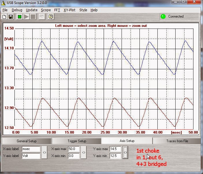

Looks like we have a clear winner there. In the datasheet configuration, the smoothing works effectively. The other way, there's almost no difference other than the voltage drop.
Onto the next stage....
An externally hosted image should be here but it was not working when we last tested it.
All I have connected up so far is the transformer, shottkeys, caps for the first 'C', the first choke and a 24ohm bleed resistor after the choke to provide approx 0.5A load.
So first up, how large should the first C stage be?
I have some 2,200uf and 1,200uf Panasonic FM caps, so I tried a few different combinations to see what the smallest value I could use that gave good smoothing.
In these graphs, Blue is before the first choke, Brown is after.
It looks to me like there's almost no difference between 5,600uf and 6,600uf. So I'll stick with 5,600uf (2 x 2,200uf and 1 x 1,200uf) for the first C stage of my CLCLC.
Next up, how to wire the chokes. I'm going for series, but there's a few ways to wire them, so I tried the method Stefan mentioned and the method from the data sheet.
Note, I have changed the graph scale here so it's clearer to see the small changes. Again, choke input above in blue, choke output, below in brown.
Looks like we have a clear winner there. In the datasheet configuration, the smoothing works effectively. The other way, there's almost no difference other than the voltage drop.
Onto the next stage....
Last edited:
This is great info!
As a thought, make it simple to remove the first C stage and listen to choke input. In the end it's the hearing that really matters!
Thanks dw!
Chuz,
Drew.
As a thought, make it simple to remove the first C stage and listen to choke input. In the end it's the hearing that really matters!
Thanks dw!
Chuz,
Drew.
onto the second 'C' and choke with an additional 47ohm bleeder to simulate the load from the dac.
Some more graphs from the scope to work out the cap size needed to smooth out the remaining AC.
So this is the second choke. As before, the blue plot on top, the input to the choke and brown plot underneath, the output.


I tested 2,200uf too, but that looked the exact same as 1,200uf.
So anything over 1,200uf seems to have no further impact on the smoothness in this stage.
But I note from Stefan's listening tests that 2 x 2,200uf sounds good in the later 2 'C' stages, so that's what I'll go for. So I have 5,600uf, 4,400uf and 4,400uf.
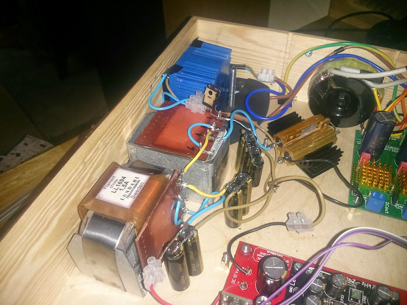
I've got it all together again using Doede's encapsulated 9v power supply, with shorter wires, a star grounding and a 57ohm (24 + 33 in series) bleeder resistor after choke 1, to give a constant 200mA load. It's now giving me 12.5v at the DAC and 11.0v at the input of the 8v shunt regs so I'm pretty happy with that.
Here it is all smashed back into my box so I can hear it. It's not my finest work..... but I thought a couple of pics would explain better what I'm up to and what's involved, if people are interested.
I'll find the time to mount it all properly and arrange and trim the wires and such when I'm happy it's all staying.

So far, just a quick listen, but I'm liking what I'm hearing a lot 🙂 Very spacious 😎
One thing that's bugging me, and it's been almost exactly the same with every power supply option I've tried is an underlying noise which I assume is mains noise? It's not loud enough that it interferes with the music, but I'd like to understand the cause. Here's a crappy short video of the sound with the amp turned right up and nothing playing.
https://www.youtube.com/watch?v=OVkah6vJn2U
There's a low hum, but there's another regular cyclical noise as well which phases in and out and gets faster and slower. I don't know whether it's a grounding issue or an interference one. Should I ground my RCAs to my power supply star ground or will that cause an issue as I'm using POS and NEG for my outputs?
cheers all,
James
Some more graphs from the scope to work out the cap size needed to smooth out the remaining AC.
So this is the second choke. As before, the blue plot on top, the input to the choke and brown plot underneath, the output.
I tested 2,200uf too, but that looked the exact same as 1,200uf.
So anything over 1,200uf seems to have no further impact on the smoothness in this stage.
But I note from Stefan's listening tests that 2 x 2,200uf sounds good in the later 2 'C' stages, so that's what I'll go for. So I have 5,600uf, 4,400uf and 4,400uf.
I've got it all together again using Doede's encapsulated 9v power supply, with shorter wires, a star grounding and a 57ohm (24 + 33 in series) bleeder resistor after choke 1, to give a constant 200mA load. It's now giving me 12.5v at the DAC and 11.0v at the input of the 8v shunt regs so I'm pretty happy with that.
Here it is all smashed back into my box so I can hear it. It's not my finest work..... but I thought a couple of pics would explain better what I'm up to and what's involved, if people are interested.
I'll find the time to mount it all properly and arrange and trim the wires and such when I'm happy it's all staying.
So far, just a quick listen, but I'm liking what I'm hearing a lot 🙂 Very spacious 😎
One thing that's bugging me, and it's been almost exactly the same with every power supply option I've tried is an underlying noise which I assume is mains noise? It's not loud enough that it interferes with the music, but I'd like to understand the cause. Here's a crappy short video of the sound with the amp turned right up and nothing playing.
https://www.youtube.com/watch?v=OVkah6vJn2U
There's a low hum, but there's another regular cyclical noise as well which phases in and out and gets faster and slower. I don't know whether it's a grounding issue or an interference one. Should I ground my RCAs to my power supply star ground or will that cause an issue as I'm using POS and NEG for my outputs?
cheers all,
James
Last edited:
- Home
- Source & Line
- Digital Line Level
- A NOS 192/24 DAC with the PCM1794 (and WaveIO USB input)