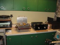
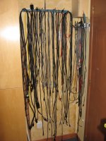
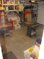
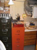
Something you didn't see is two full racks of test cables, test probes, scope probes that I got for free! I took them from the garbage dumpster once they close the shop. Also they were throwing away a very nice custom made bench (see the green door one). Got this one for free, including wood storage boxes that fit inside the lower section to neatly class spare parts.
The scavenger was there, me 😀
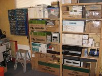
I have also the usual assortment of parts bins, parts shelves, etc...So it is my own cavern in the basement, with test sound system.
The scavenger was there, me 😀
I have also the usual assortment of parts bins, parts shelves, etc...So it is my own cavern in the basement, with test sound system.
Attachments
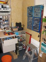
I have three shops really in my home (and an understanding wife). My electronic room that you just saw, the usual garage for the metal, drilling, cutting works and a smaller corner I made for myself in the ventilation room where I make my pcb, equipped with exposition table, dremel and even a big sink for the developer, etc. I do the etching in the garage because of the full smells of the etching solution.
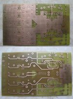
I'll do my own D1 prototype PCB there over the weekend.
I'll do my own D1 prototype PCB there over the weekend.
Attachments
One question I had is that in your instructions you said to adjust 24V on R1 (Id 120ma), but then you're saying 21V, and indicating 21V on your schematic. 21V is not 120ma Id. What is the correct voltage 24 or 21V? Thanks...
Hi Algar,
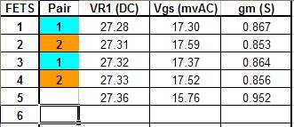
You're definitely getting good results if your transconductance numbers are between 0.8 and 1. If you have a large enough batch, you should be able to find two tightly matched pairs that are in the upper 0.9 region. Those are the ones you want!
Keep good track of all your numbers as I'm sure there are people here who would be interested in matched pairs if you have extras.
If you want to do a consistency check, re-measure one of the earlier ones and see if you get roughly the same number.
Keep up the good work, and kudos on the very nice test bench!
Cheers,
Owen
Thanks for the confirmation. I should have completed the batch this weekend. I let them stabilize for about 15 min. while watching TV.
One question I had is that in your instructions you said to adjust 24V on R1 (Id 120ma), but then you're saying 21V, and indicating 21V on your schematic. 21V is not 120ma Id. What is the correct voltage 24 or 21V? Thanks...
i assume this question is for Owen yes? yeah i had this same confusion at first. its definitely 24. check the scheme i posted, it has the voltages noted on it as well. i think opc wrote down a Freudian slip and wrote VDS, which is generally about 21 when the voltage across R1 is 24
yeah you tend to get a group that are similar then a jump. those numbers look right, but they are pretty low for these fets. i discarded anything below 0.9s or rather i still have them, but i didnt have them in the pool for matched sets.
Last edited:
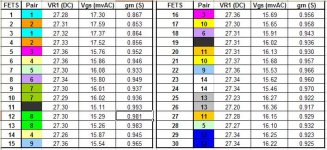
Here the final match results. I know my AC results are much lower than yours. It may be my setup. I'll recheck them into the actual circuit.
Attachments
Last edited:
I removed my own order.
1. cersepn x 1
2. icewall x 2
3. pmchoong x 1
4. qusp x 1 this is tentative mate, but wanted to make sure my name was down
5. regal
6. randytsuch x 1
7. LK x1
8. greyrab x1
9. alexcount x1
10. adelias x1
11. Coolhead x1
12. Emphrygian x 1
13. tranhieu x 1
14. crazyfrog x 1
15. woresseo x 2
16. Pedefede x 1
17. ggetzoff x 1
18. syklab x1 + fets
19. Magsy x 1
Very nicely done! Wow!
You must have a pretty decent home etching setup!
Post some pictures with the completed unit when you get it all done. I'd very much like to see how it turns out.
Cheers,
Owen
You must have a pretty decent home etching setup!
Post some pictures with the completed unit when you get it all done. I'd very much like to see how it turns out.
Cheers,
Owen
i would not use te 0.97.5-99s parts or at least retest. i did not get anything this high testing 150+ devices, my guess looking at those numbers is that low and fluctuating temperature has played a part, as overall mine were grouped closer than that. maybe you got a batch that was particularly high, but it seems unlikely. in fact even .95,96 was only encountered in error in a few which was lower when retested. particularly since you have some that are very low by my group too
nice work on the PCB, looks good!
nice work on the PCB, looks good!
Last edited:
The FET was getting barely warm with 24V on R1. R1 was much hotter. Maybe my heatsink was too big and the FET wasn't warming up enough. I'll retest in the actual circuit with the cut to lenght heatsink.
Hi. I'm still not ready to sell any match pairs. As I said on the post, I want to retest all of them in the actual circuit first. It may take me 1-2 weeks before I'm ready. I'll post it here when I'm ready. I won't warranty anything, because I want to be sure you'll get two good pairs. BTW I'll accept PayPal with 3% fee, and yes I'll ship worldwide.
Thanks...
Thanks...
Output coupling capacitor question: The final schematic is showing 1800uF electrolytic output cap, in parallel with the 22uF film cap. Do I need these electrolytic caps? Tx. Original D1 used 220uF bypassed by 0.047uF film.
Last edited:
no, these are optional in case someone wants to save a bit of cash i guess. just use the film sized to give best 3db point vs your amps input Z, i'm using 4.7uf auricap bypassed with 0.1u copper/ptfe
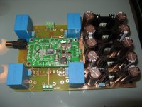
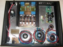
Almost ready to start mounting everything into an enclosure. I recycled a Cambridge Audio DVD that I had and stop to work years ago. I removed all the junk from it, and this will make a nice case.
I kept the player small headphone amplifier output PCB. I'll connect it to the single ended output. It is probably not good, but at least the front panel will look perfect.
You can see the Antek power transformers, the D1 and its heatsinks, the original Twisted Pear Ballsie balanced to single-ended converter, their LCBPS bi-polar supply for the Ballsie, and my small TentLabs 6.6V shunt reg for the ESS Dac Va supply.
It should all fits nicely.
Attachments
Me wants boards!
Hi Owen,
Please put me down for 2x NTD1 PCBs
Any marched mosfets left?
Ciao!
Do
Hi Owen,
Please put me down for 2x NTD1 PCBs
Any marched mosfets left?
Ciao!
Do
- Home
- Source & Line
- Digital Line Level
- A New Take on the Classic Pass Labs D1 with an ESS Dac