The current (!) generation of Quad products use current dumping
https://quad-hifi.co.uk/products/artera-stereo (about UKP1,300) 140W per channel into 8 ohms.
https://quad-hifi.co.uk/products/artera-mono (about UKP1,300 each), but those give 300W into 8 ohms and 400W into 4 ohms!
https://quad-hifi.co.uk/products/artera-stereo (about UKP1,300) 140W per channel into 8 ohms.
https://quad-hifi.co.uk/products/artera-mono (about UKP1,300 each), but those give 300W into 8 ohms and 400W into 4 ohms!

Then I present a preliminary design of my personal 30W Current Dumper, based on the current inspirations of the DIY forum.

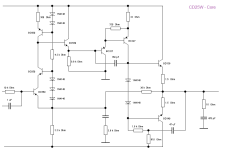
The amplifier design will be called CD30W.
HBt.
The amplifier design will be called CD30W.
HBt.
Because the original is QC, I'm currently trying the original approach.Why quasi instead of complementary?
But:
see below, everything in Watt_peak - the CD alone is not satisfactory at the moment.
Attachments

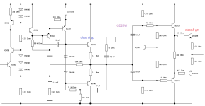
Good approach, I'll try it out right away with the slanted design (the framework conditions). See below. This class A approach can be controlled without clipping up to 40Vpp and is intended to represent the feedforward branch.1. A low distortion Class A amp that can provide about 50mA current in Class A. If you make the Class A stage in push-pull instead of single ended, you can just half the bias current. With only 25mA, you don't even need to mount it on the main heat sink. A small to-126/to-220 heatsink is sufficient.
It is sensible to use the familiar EF-2 approach. It is still missing in my experiment.2. A high current gain dumper with no voltage gain. I am not satisfied the dumper from Quad amps, which was made of "Quasi Complementary". As these days, PNP power transistors are widely available, I recommend using CFP to create a dumper instead.
Exactly, and then you can vary the bias and determine exactly which mechanisms are responsible for the effective advertising slogan "current dumper". To do this, we carry out several real-life measurements in the frequency range from 0Hz to 7kHz. Amounts are of secondary importance, we need the real and imaginary components of the respective responsible currents.3. Combine them with a bridge.
Attachments
The next step is the final stage, a push-pull impedance converter with (instantaneous and optimum bias) Iq=60mAdc.
It is possible that both amplifiers will be equipped with separate (automatic) DC offset corrections.
Once the function test has been passed, the first thing to do is to log the error to be corrected. Then install the bridge ..!
It is possible that both amplifiers will be equipped with separate (automatic) DC offset corrections.
Once the function test has been passed, the first thing to do is to log the error to be corrected. Then install the bridge ..!
Attachments
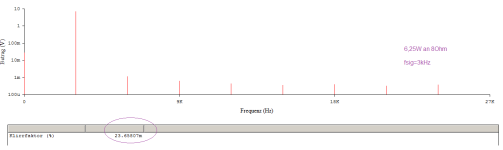
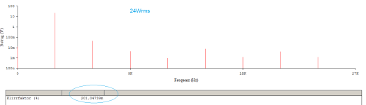
15.5Wrms at 3kHz
Here one can check in advance, even implement as a permanent monitor in the final amplifier (as a display), whether an error-correcting gizmo will bring any dubious gain at all.
If it does not cause any damage, this feature can run with a clear conscience.
The CD25W amplifier does not need this gadget unless the manufacturer wants to advertise it.
HBt.
You need resistors in the emitters of the output CFPs.
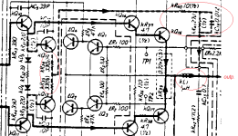
BTW the same approach was used by Sansui in early 1980s and marketed as "Sansui Super Feef Forward System". Here is Sansui AU-D33:

It actually works, and this Sansui amp sound very nice.
BTW the same approach was used by Sansui in early 1980s and marketed as "Sansui Super Feef Forward System". Here is Sansui AU-D33:
It actually works, and this Sansui amp sound very nice.
Flip the single end input stage, then I can use the high voltage n-channel mosfet as the input stage. There is no current loss. All the distortion is canceled out.
If you swap out the mosfet with 2n5551, I believe in the real world you would never be able to tell the difference as the current loss at the base of the bjt is usually below 1%. All other parts may have larger variance.

If you swap out the mosfet with 2n5551, I believe in the real world you would never be able to tell the difference as the current loss at the base of the bjt is usually below 1%. All other parts may have larger variance.
Last edited:
Dear
@Bernhard
don't we want to try together with our simulators to get the very best out of this idea of “two independent amplifiers” for the /into Current Dumper-Transformation?

What do you think? Does the concept have enough potential to correct the very last bit of garbage out of the distortion bed using feedforward?
greetings,
HBt.
@Bernhard
don't we want to try together with our simulators to get the very best out of this idea of “two independent amplifiers” for the /into Current Dumper-Transformation?
What do you think? Does the concept have enough potential to correct the very last bit of garbage out of the distortion bed using feedforward?
greetings,
HBt.
Update:


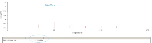
Now, by a true miracle, the standalone push-pull power amplifier has become a /the dumper. The pseudo bridge elements have been calculated correctly and now the all-important FFT is waiting to be used.
HBt.
Now, by a true miracle, the standalone push-pull power amplifier has become a /the dumper. The pseudo bridge elements have been calculated correctly and now the all-important FFT is waiting to be used.
HBt.

- Home
- Amplifiers
- Solid State
- A new beginning: Optimize a QUAD 405 core