Ursuppe
Since I don't want to further contaminate @jxdking s nice thread, I hereby start a container for all new thoughts on the Quad-405 dinosaur.


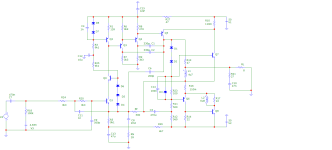
0.001% THD horizontal without TMC, only current dumping!

Dear reader,
please see the Ursuppe thread. We still have to find a way to hopefully get 50 real watts out of the amplifier core.
Q9 is MPSA43.
HBt.
Since I don't want to further contaminate @jxdking s nice thread, I hereby start a container for all new thoughts on the Quad-405 dinosaur.
0.001% THD horizontal without TMC, only current dumping!
Dear reader,
please see the Ursuppe thread. We still have to find a way to hopefully get 50 real watts out of the amplifier core.
Q9 is MPSA43.
HBt.
Dinosaur should be reserved to the venerable tubes who dominated the audio domain for roughly half a century,
this one is rather one of those early and clumsy mammals.
As for power dunno how you have any issue since it can deliver 100W RMS/8R with the original schematics.
this one is rather one of those early and clumsy mammals.
As for power dunno how you have any issue since it can deliver 100W RMS/8R with the original schematics.
Good morning!As for power dunno how you have any issue since it can deliver 100W RMS/8R with the original schematics.
I use exactly the same components that you use in your study (in the thread). The simulation program you are using must also announce problems with a power consumption of more than 20W. Did you conceal this or did you not consider it?
But I've just seen that you've changed the components again without any indication - and are also staying below 25W with your Sims.
#
But none of that matters, because in the end it was all about the comparison between bias currents, the effect of local and global feedback, as well as the question of what is actually in the Miller loop and whether 'CD' is not a feedforward-error-take-away number at all, but hidden gnfb alone.
Never mind, I'll compare my simulation above with the cascode and CD of your last TMC, multipole compensation methods: the circuit above achieves a horizontal THD of -100dB with 23dB voltage gain (and that almost independent of load).
Your TMC throw should be a generously estimated -140dB THD, below +11dB CLG.
I'm sorry, but I don't believe in the “utopian THD”. Can your simulator calculate and output the THD for us?
kindly,
HBt.
I would like this to be understood lovingly.‘Dinosaur’?

The horizontal axis is not Watts (W), it is dBW. The rise in THD is at around 20dBW. Divide by 10, and do 10 to the power of that to get 100W when the distortion rises.
Which means the sim is working just fine.
Craig
Which means the sim is working just fine.
Craig
Oh my God, of course, it must be my chronic lack of sleep as well as the rust in my CPU.
Thank you very much Craig,
of course the X-axis is in dBW
10 * log_10 (Power / 1W)
I of all people should not have made this faux pas, I'm definitely getting old. Perhaps I should (also) follow the permanent health offers and medical check-ups. That's embarrassing.
HBt.
Thank you very much Craig,
of course the X-axis is in dBW
10 * log_10 (Power / 1W)
I of all people should not have made this faux pas, I'm definitely getting old. Perhaps I should (also) follow the permanent health offers and medical check-ups. That's embarrassing.
HBt.
Good morning!
Your TMC throw should be a generously estimated -140dB THD, below +11dB CLG.
I'm sorry, but I don't believe in the “utopian THD”. Can your simulator calculate and output the THD for us?
Good morning as well, and there s nothing like -140db in any of my regular sims, the one with 1k TMC resistance
has other harmonics than H2 at about -120dB for the strongest, H2 is at -103dB, and that s at 25W RMS and within
a 20kHz BW, at ultrasonic frequencies the levels are higher.
That's great, and above you can see -100dB (without TMC, but with CD and less negative feedback) even at 100W, all horizontal ..!(...) H2 is at -103dB, and that s at 25W RMS and within
a 20kHz BW, at ultrasonic frequencies the levels are higher.
What does that look like in your simulator?

I put Quad 909 for your reference, as it was the last current dumping from Quad.
https://www.diyaudio.com/community/attachments/quad-909-schematic-pdf.1219124/
https://www.diyaudio.com/community/attachments/quad-909-schematic-pdf.1219124/
It remains single ended at all times. It doesn’t suddenly grow a complementary output device.the so-called Class A component /or Amp remains single-ended up to 80mWrms.
Nothing ‘so-called’ about it either.
You're absolutely RIGHT. Unfortunately, my "so-called" does not refer to this raisin. Several pieces of information are hidden in the message.It remains single ended at all times. It doesn’t suddenly grow a complementary output device.
Nothing ‘so-called’ about it either.
Bye

Thank you, that is very informative - interesting (from the year 2000). Technical data?I put Quad 909 for your reference, as it was the last current dumping from Quad.
@stocktrader200
I think the THD (as an indicator) can no longer be greatly improved. Other aspects certainly can.
HBt.
I think the THD (as an indicator) can no longer be greatly improved. Other aspects certainly can.
HBt.
QUAD909
The last flagship. However, the question now is whether this Current dumper was the best of the entire family, i.e. the end of the art of engineering.
I still believe current dumping will be best topology to make an amp.However, the question now is whether this Current dumper was the best of the entire family, i.e. the end of the art of engineering.
My approach would be divide-and-conquer. Here is how to make a perfect current dumping amp.
1. A low distortion Class A amp that can provide about 50mA current in Class A. If you make the Class A stage in push-pull instead of single ended, you can just half the bias current. With only 25mA, you don't even need to mount it on the main heat sink. A small to-126/to-220 heatsink is sufficient.
2. A high current gain dumper with no voltage gain. I am not satisfied the dumper from Quad amps, which was made of "Quasi Complementary". As these days, PNP power transistors are widely available, I recommend using CFP to create a dumper instead.
3. Combine them with a bridge.
PS: I will post the design later.
Last edited:
- Home
- Amplifiers
- Solid State
- A new beginning: Optimize a QUAD 405 core