Sim looks OK. It may not sound so smooth. Your room gain will be a large factor. Note bass woofer inverted phase.
To wire it. Draw it out on a board and place the components over the diagram.
Thanks; which sim are you referring to (there are several now).
Good point on just drawing it out. Duh. Hahah...

Very best,
1. Acoustic.. covered in post #2, the lows would tend to work together and the highs would tend to be separate,Namely I just wanted to make sure that if I did a crossover like you showed above and the two 4ohm drivers were wired in series for 8ohm and then soldered to that crossover, that it would be similar to the above or if it would be different.
...
That said, do you think that changes how to design the crossover circuit or any other considerations on the crossover circuit, the one driver facing up and not really aligning with the other driver?
2. Electrical.. covered in post #9, the impedance would be double,
3. Level.. for series the sensitivity would be the same as a single driver at the lower frequencies but for parallel it would be +6 that of a single driver.

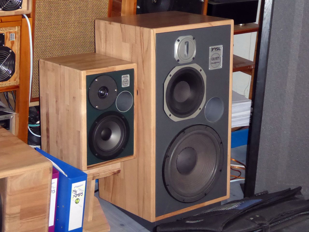
May I suggest you, @MalVeauX, to test the simple configuration below ? You may be pleasantly surprised, who knows...

Where Tweeter are your 2x 4" Wide-Band speakers, and Woofer your 8" speaker.
Where, for a Fc = 212Hz, you choose C=56µF and L=10mH (ferrite or lamination core for minimum Rs, of course) and add if needed a fixed L-pad for your 2x 4". This is the same calculation method as the // 6dB/Oct. Xover, but not the same sonic behavior at all...
I used this serial configuration on several 2-ways and 3-ways DIY speakers with great success, after comparison with // 6 and 12dB/Oct. - see below :
For the Bookshelf 2-Ways :


For the Monitor 3-Ways :


But it's me, OK ? 😉
T
Where Tweeter are your 2x 4" Wide-Band speakers, and Woofer your 8" speaker.
Where, for a Fc = 212Hz, you choose C=56µF and L=10mH (ferrite or lamination core for minimum Rs, of course) and add if needed a fixed L-pad for your 2x 4". This is the same calculation method as the // 6dB/Oct. Xover, but not the same sonic behavior at all...
I used this serial configuration on several 2-ways and 3-ways DIY speakers with great success, after comparison with // 6 and 12dB/Oct. - see below :
For the Bookshelf 2-Ways :
For the Monitor 3-Ways :
But it's me, OK ? 😉
T
May I suggest you, @MalVeauX, to test the simple configuration below ? You may be pleasantly surprised, who knows...
Interesting stuff, will explore this! Thanks!
Very best,
You have picked a tricky project to be learning to use *.frd files etc, due to the acoustic complexity. In it's current form, the sim is useful for determining impedance interactions, filter slopes etc..I am not really going for flat, a slight `V' response simply due to preference, as I like a little more warmth and a kiss of sparkle for stereo music listening (keeping in mind these will not be corner loaded nor up against a wall, but away from the wall in a room).
However it's not ideal for estimating the tonal balance. Some of this you'll probably choose to do by ear, and then you can retroactively determine what you've done in the sim in autopsy style.
Could be just what you want in this situation.any thoughts on incorporating an Lpad like this
If any of us ever get there 😉I can build the crossover externally which allows me to swap polarity and test everything externally before putting it together permanently I think.
Could be just what you want in this situation.
If any of us ever get there 😉
Thanks!
I think I'll try to use one, seems like a much simpler way to attenuate things by ear in a room. I like dials and knobs anyways.
Once I like something I leave it alone and move on to the next project. Part of the fun. 🙂
Very best,
My SIM. I wouldn't criticise someone else's ideas.Thanks; which sim are you referring to (there are several now).
Good point on just drawing it out. Duh. Hahah...
Very best,
My SIM. I wouldn't criticise someone else's ideas.
Ok thanks; no worries, I don't take it as criticism at all, more just helping to identify something to someone who may not have. I appreciate it.
Very best,
Update,
Tried a few things, changed out drivers to a new one Dayton offers that is really inexpensive (CE78PF) which is a 3" full range that handles 10w and is 4ohm. Two of them in series would be 8ohm and handle 20w. So I modeled a few things to see how they match with the GRS 8SW4HE bass driver at 4ohm and 20w too.
I think I'm a little closer to something workable on this Xsim crossover model. I'm wondering if there's a clever way I'm missing to help address 2khz~3khz range and the 11khz spike. If I can't, that's ok. If anything I am mainly interested in how to address the 2khz~3khz trough primarily. I'm ok with the spike at 11khz if I had to keep it. I tried to pay more attention to phase in this one.
I've attached this new model for anyone to tweak.

How the bass driver looks modeled at the same power in a bass reflex chamber, the CE78PFs in a sealed chamber, both getting 20w. Crossed at 300hz, the full range drivers have no risk of xmax limits. The bass driver doesn't see xmax at 40w until 15hz so safe to say I don't need a high pass filter there.

Thanks!
Very best,
Tried a few things, changed out drivers to a new one Dayton offers that is really inexpensive (CE78PF) which is a 3" full range that handles 10w and is 4ohm. Two of them in series would be 8ohm and handle 20w. So I modeled a few things to see how they match with the GRS 8SW4HE bass driver at 4ohm and 20w too.
I think I'm a little closer to something workable on this Xsim crossover model. I'm wondering if there's a clever way I'm missing to help address 2khz~3khz range and the 11khz spike. If I can't, that's ok. If anything I am mainly interested in how to address the 2khz~3khz trough primarily. I'm ok with the spike at 11khz if I had to keep it. I tried to pay more attention to phase in this one.
I've attached this new model for anyone to tweak.
How the bass driver looks modeled at the same power in a bass reflex chamber, the CE78PFs in a sealed chamber, both getting 20w. Crossed at 300hz, the full range drivers have no risk of xmax limits. The bass driver doesn't see xmax at 40w until 15hz so safe to say I don't need a high pass filter there.
Thanks!
Very best,
So I entered your design shown above and replicated the results shown. A few things I noticed. 1. The 2.0 ohm minimum impedance is probably not the greatest thing for some amplifiers. 2. To test a crossover I flip the phase on one driver and look to see that there is a deep notch at the crossover frequency. This happens if the phase is correct. I flipped the phase on your woofer and the plot showed a very shallow notch of maybe 5 dB, so that could be improved. Here is the plot below, with the phase reversed on your design showing the notch at 250 Hz.

Figure 1. Original design, Amplitude response with woofer phase reversed to show notch at crossover frequency.
I took a shot at a design using the 2nd Order Lowpass and Highpass circuit blocks. These are handy as they calculate the part values for you when the frequency, Q and impedance are entered. So I used 250 Hz, Q = 0.707 and Z = 4 ohms for the woofer etc. I went back and made adjustments after matching the midrange levels to the woofer and then adjusted to get flat response or deep notch when the phase of the woofer is switched. As this is 2nd order Butterworth alignment the normal setting is reversed phase on woofer vs. midranges.

Figure 2. New design using Circuit Blocks, Amplitude response.

Figure 3. Amplitude response test with the phase flipped on the woofer, showing the desired deep notch at crossover frequency which ended up closer to 200 Hz.

Figure 4. impedance plot. The minimum impedance is now 3.5 ohms up from 2.0 ohms.

Figure 5. Schematic of crossover showing use of Circuit Blocks.
Here is the schematic. Yes, the phase must be reversed ( Top terminal on driver shows minus sign) on the upper drivers to achieve the proper 2nd order crossover with this damping ratio Q = .707
There is a "bug" in Xsim, as it looses track of the location of the Circuit Block folder when you save a file anywhere else. You can navigate back to the circuit block folder here: /Users/Public/XSim/CircuitBlocks/ Of course you can just enter the part values shown and adjust them to values that can be purchased.
If the two midrange drivers are connected in parallel a much smaller coil will be required. You would just have to go in and adjust the Circuit Block impedance to 4 ohms and adjust that resistor value. You could also raise the crossover frequency to get smaller coil and cap values. Just get in there and twist the frequency knobs on those filter blocks. Good fun.
I hope you find this example useful.
Figure 1. Original design, Amplitude response with woofer phase reversed to show notch at crossover frequency.
I took a shot at a design using the 2nd Order Lowpass and Highpass circuit blocks. These are handy as they calculate the part values for you when the frequency, Q and impedance are entered. So I used 250 Hz, Q = 0.707 and Z = 4 ohms for the woofer etc. I went back and made adjustments after matching the midrange levels to the woofer and then adjusted to get flat response or deep notch when the phase of the woofer is switched. As this is 2nd order Butterworth alignment the normal setting is reversed phase on woofer vs. midranges.
Figure 2. New design using Circuit Blocks, Amplitude response.
Figure 3. Amplitude response test with the phase flipped on the woofer, showing the desired deep notch at crossover frequency which ended up closer to 200 Hz.
Figure 4. impedance plot. The minimum impedance is now 3.5 ohms up from 2.0 ohms.
Figure 5. Schematic of crossover showing use of Circuit Blocks.
Here is the schematic. Yes, the phase must be reversed ( Top terminal on driver shows minus sign) on the upper drivers to achieve the proper 2nd order crossover with this damping ratio Q = .707
There is a "bug" in Xsim, as it looses track of the location of the Circuit Block folder when you save a file anywhere else. You can navigate back to the circuit block folder here: /Users/Public/XSim/CircuitBlocks/ Of course you can just enter the part values shown and adjust them to values that can be purchased.
If the two midrange drivers are connected in parallel a much smaller coil will be required. You would just have to go in and adjust the Circuit Block impedance to 4 ohms and adjust that resistor value. You could also raise the crossover frequency to get smaller coil and cap values. Just get in there and twist the frequency knobs on those filter blocks. Good fun.
I hope you find this example useful.
Attachments
Last edited:
Here is the schematic. Yes, the phase must be reversed ( Top terminal on driver shows minus sign) on the upper drivers to achieve the proper 2nd order crossover with this damping ratio Q = .707
There is a "bug" in Xsim, as it looses track of the location of the Circuit Block folder when you save a file anywhere else. You can navigate back to the circuit block folder here: /Users/Public/XSim/CircuitBlocks/ Of course you can just enter the part values shown and adjust them to values that can be purchased.
If the two midrange drivers are connected in parallel a much smaller coil will be required. You would just have to go in and adjust the Circuit Block impedance to 4 ohms and adjust that resistor value. You could also raise the crossover frequency to get smaller coil and cap values. Just get in there and twist the frequency knobs on those filter blocks. Good fun.
I hope you find this example useful.
Thank you so much, an awesome lesson! I didn't pay attention to the impedance dropping down to 2ohm there as you mentioned, that's very good to catch. Lots of great points for me to study and try things with. I really appreciate you taking the time to help.
I'll see how it works on that design with the RS100 drivers that you re-modeled and see if I can do similar with this information with the CE78PF driver in the last design.

Very best,
Distortion gets down if you put resistors in series to the drivers.
Try putting the Dayton in parallel with 1, 2, or more ohms in series. I would try 6db first for them instead 12db topology.
You can leave then the 10 ohms for the bass out.
Next I would try series topology filter first instead of parallel for bass and the small Dayton. Could be you get away with 6 and 6db filter and have better phase response.
MalVeauX, I've just run up this thread. It's something I've been meaning to do for a long time now.
https://www.diyaudio.com/community/threads/xsim-configuring-the-plot-window.406106
https://www.diyaudio.com/community/threads/xsim-configuring-the-plot-window.406106
The series-1st-order XO has been my go-to since first-time diy (AMT/honeycomb), after listening test against the usual parallel-1st-order. I had read that the difference could not be sim'ed -- but that's hard to believe. In my case(s) I brought the series LP and HP filter frequencies (calculated for parallel) somewhat past each other, judged by ear, since each driver's bypass (inductor for tweeter, capacitor for woofer) ought to have made the series XO closer to 2nd-order than 1st-order. Would there not be a dip otherwise? Further elucidation appreciated.May I suggest you, @MalVeauX, to test the simple configuration below ? You may be pleasantly surprised, who knows...
View attachment 1239606
Where Tweeter are your 2x 4" Wide-Band speakers, and Woofer your 8" speaker.
Where, for a Fc = 212Hz, you choose C=56µF and L=10mH (ferrite or lamination core for minimum Rs, of course) and add if needed a fixed L-pad for your 2x 4". This is the same calculation method as the // 6dB/Oct. Xover, but not the same sonic behavior at all...
I used this serial configuration on several 2-ways and 3-ways DIY speakers with great success
The series-1st-order XO has been my go-to since first-time diy (AMT/honeycomb), after listening test against the usual parallel-1st-order. I had read that the difference could not be sim'ed -- but that's hard to believe. In my case(s) I brought the series LP and HP filter frequencies (calculated for parallel) somewhat past each other, judged by ear, since each driver's bypass (inductor for tweeter, capacitor for woofer) ought to have made the series XO closer to 2nd-order than 1st-order. Would there not be a dip otherwise? Further elucidation appreciated.
Yes. That's it. The behavior of the Serial 1st Order is closer to a 2nd Order than a 1st Order - unlike the parallel 1st Order equivalent...
I made several tests on 2-ways and 3-ways projects in 1st Order //, 1st Order S and 2nd Order // : each time the 1st Order S won - except one time, but the speaker association was so poor that I had to shift for a 2nd order with much compensations, before giving up the project !
Sorry, I have no rational explanations to provide, just my listening experimentations with Audio friends, for which we stayed as objective as possible to ascertain that there was a qualifiable difference, not impressions - this with all other parameters equal otherwise, of course : same speakers, same enclosures, same amplification and source, A/B instant tests on repeated music samples... And yes, there was a difference, clearly at the advantage of the 1st Order Serie.
I think that the advantages of the 1st Order Series crossovers are the following :
1 - in Series, all speakers are connected in the same polarity, meaning that all impulse or step response is in the same polarity too. The cones of the speakers will move in the same direction on the transients. This is not the case with // 1st Order, and most of higher orders.
2 - the 1st order offers ideal phase and group delay, being S or //. Add this quality to the point 1 above belonging to the Serial configuration, and you understand why your speakers reacts exactly together. This made my Daughter (not Audiophile for a cent) say about the 1st Order S : "these speakers are really Synchro".
3 - simplicity : less components drives to less losses in them, and moreover, that fact that the speakers are connected directly each other (in Serie) leds to less insertion losses.
4 - about the increased slope, closer to 12dB/Oct., I'd say that each speaker in 6dB/Oct. Series formula "sees" a LC network, unlike on a // 6dB/Oct. where each speaker "sees" a L or a C. 12dB/Oct are LC networks too, so it can be a possible interpretation of the phenomenon...
Yes, there's not much litterature about that subject... But the test of the simple 6dB/Oct. Serie crossover is worth to do, IMHO and regarding my personal experience !
Below an article about Series and // 6dB/Oct. comparison :
https://sound-au.com/parallel-series.htm
Another one - in French - revisiting the concepts of Mr. Bakegaard, from Bang & Olufsen :
http://jimbee.over-blog.com/page-5371974.html
T
That's great info, thanks!MalVeauX, I've just run up this thread. It's something I've been meaning to do for a long time now.
https://www.diyaudio.com/community/threads/xsim-configuring-the-plot-window.406106
Very best,
A few observations regarding first order and series crossovers.
1. A speaker with first order crossovers can sound very entertaining and produce what I think of as a bigger sound source as the drivers have overlapping responses. So rather than having an even or uniform directivity pattern from each driver you have lobes of higher and lower intensity in different directions. This can be an enjoyable special sort of surround effect. It is very apparent when listening to a single speaker and switching between a first order and a higher order crossover, say a 4th order Linkwitz Reily design that is very commonly used in professional gear. The speaker with a first order crossover will produce almost a simulated stereo effect from the single speaker compared to the narrow source disappearing act of a speaker with a high order crossover. Wilson Audio sells lots of speakers using this effect. A miniDSP digital crossover can switch between the two using a remote control. With the first order crossover the sound seems to locate more across the front surface of the speaker. Not good or bad, just different.
2. Series crossovers don't produce a clean 1st or 2nd order response as the the electrical characteristics of one driver will modify the attenuation of the signal going to the other driver. So the signal to a woofer may roll off steeply for an octave and then flatten out for an octave before rolling off some more.
3. First order and simple series crossovers will not roll off the out of band signal fast enough for many speakers to avoid low frequency distortion from a tweeter or midrange as too much low frequency moves the cone out of its linear range or may excite cabinet wall, acoustic and cone breakup modes in the high frequencies of woofers and midranges. Again these can actually make for a "fuller" or entertaining sound from this distortion and resonances that might be preferred in some A/B listening tests with some musical content but will damage the ultimate fidelity and clarity of the speaker.
The distortion results can be easily measured and compared for different crossovers once the speaker is built. The directivity pattern and maximum SPL are complex and time consuming to measure but can be easily simulated using very good free speaker design software such as Visaton Boxsim and VituixCad.
Here is an example of the response of each driver from the Magnepan 3.7i speaker that uses a series crossover. Note the slope changes in the response of the woofer. This really doomed the horizontal radiation pattern of this speaker. It's frequency response has wild swings with horizontal angles. Maybe this is just a poor example of a series crossover and someone more skilled in the art could do better.


Below Ohm Acoustics L loudspeaker with stock 1st order crossover has a ragged dispersion pattern.

Here is the same speaker with an updated 2nd order crossover. Note the large segment of even dispersion in red. The beam width transition between the woofer and tweeter is very apparent at around 1,500 Hz.

1. A speaker with first order crossovers can sound very entertaining and produce what I think of as a bigger sound source as the drivers have overlapping responses. So rather than having an even or uniform directivity pattern from each driver you have lobes of higher and lower intensity in different directions. This can be an enjoyable special sort of surround effect. It is very apparent when listening to a single speaker and switching between a first order and a higher order crossover, say a 4th order Linkwitz Reily design that is very commonly used in professional gear. The speaker with a first order crossover will produce almost a simulated stereo effect from the single speaker compared to the narrow source disappearing act of a speaker with a high order crossover. Wilson Audio sells lots of speakers using this effect. A miniDSP digital crossover can switch between the two using a remote control. With the first order crossover the sound seems to locate more across the front surface of the speaker. Not good or bad, just different.
2. Series crossovers don't produce a clean 1st or 2nd order response as the the electrical characteristics of one driver will modify the attenuation of the signal going to the other driver. So the signal to a woofer may roll off steeply for an octave and then flatten out for an octave before rolling off some more.
3. First order and simple series crossovers will not roll off the out of band signal fast enough for many speakers to avoid low frequency distortion from a tweeter or midrange as too much low frequency moves the cone out of its linear range or may excite cabinet wall, acoustic and cone breakup modes in the high frequencies of woofers and midranges. Again these can actually make for a "fuller" or entertaining sound from this distortion and resonances that might be preferred in some A/B listening tests with some musical content but will damage the ultimate fidelity and clarity of the speaker.
The distortion results can be easily measured and compared for different crossovers once the speaker is built. The directivity pattern and maximum SPL are complex and time consuming to measure but can be easily simulated using very good free speaker design software such as Visaton Boxsim and VituixCad.
Here is an example of the response of each driver from the Magnepan 3.7i speaker that uses a series crossover. Note the slope changes in the response of the woofer. This really doomed the horizontal radiation pattern of this speaker. It's frequency response has wild swings with horizontal angles. Maybe this is just a poor example of a series crossover and someone more skilled in the art could do better.
Below Ohm Acoustics L loudspeaker with stock 1st order crossover has a ragged dispersion pattern.
Here is the same speaker with an updated 2nd order crossover. Note the large segment of even dispersion in red. The beam width transition between the woofer and tweeter is very apparent at around 1,500 Hz.
Perhaps give Xmachina a twirl? Seems quite nifty (have not tried myself!).
https://www.diyaudio.com/community/threads/automatic-crossover-designing-with-xmachina.316283/
I mean if you wanted yet another option 🙂
//
https://www.diyaudio.com/community/threads/automatic-crossover-designing-with-xmachina.316283/
I mean if you wanted yet another option 🙂
//
- Home
- Loudspeakers
- Multi-Way
- A little crossover advice or help (full range driver and bass woofer)