Yeah they are kinda loose. But not loose loose like the Chinese magnovals. They are far worse. But supposedly one can stick compactron socket pins in them to make them work. I can’t see sacrificing perfectly good 12 pin sockets, because those are rare enough as it is. Last place I tried to buy a bunch from put a limit on the quantity.
I don't think I even have a footprint for a 12-pin PCB socket in Orcad, but I have a bunch of the usual lug-based 12 pin sockets, which I could always use with tubes on top and pigtails to the PCB beneath them.
St. Louis-He left Florida some time ago and went somewhere other than Tennessee, in the Midwest maybe. I guess he moved again. He has always had a store on Ebay, that's where I found him when he was in Florida.
Was planning a visit to see his shop since I'm thru there often, but he was in process of moving- guess to TN.
Yes-Yeah they are kinda loose. But not loose loose like the Chinese magnovals. They are far worse. But supposedly one can stick compactron socket pins in them to make them work.
Can transfer compactron pins into magnoval bases if both are Chinese porcelain bases, but it's tedious.
I've had good luck ordering compactrons from this store-I can’t see sacrificing perfectly good 12 pin sockets, because those are rare enough as it is. Last place I tried to buy a bunch from put a limit on the quantity.
https://www.aliexpress.us/item/2251832517608384.html?
Mounting brackets are sturdier than the other ChiFi design, IMO
Jim
I may have a 12 pin footprint in my CAD software. Would send to you, if interested. It would be .dxf or .dwg format.I don't think I even have a footprint for a 12-pin PCB socket in Orcad, but I have a bunch of the usual lug-based 12 pin sockets, which I could always use with tubes on top and pigtails to the PCB beneath them.
Jim
I've been pecking slowly away at the schematic and layout for this contraption, getting the autobias circuit figured out, and straightening out the reference designators on the schematic while I'm at it. What remains is choosing suitable values for the load resistors on the input folded cascode stage for proper bias on the output stage. The DC-DC converter I will use will supply +350V, +175V, and -50V for bias. I'm running the filaments on the 6LR8s directly in a series string from the 24V SMPS adapter that powers everything - a little bit of undervoltage on the filaments, but I'm willing to accept that. I'll use a simple series-pass regulator to drop the screen supply from 175V to 120V.
Seems like 120 is the right number for a lot of sweep tubes, these included. At vg2=120, these “act” like 7868’s. *JN7’s act like EL34’s, and *DQ5’s act like 6550’s. And 55 volts of drop you can find a mosfet that won’t do something stupid. Or you can use a “darlington” of a mosfet and an MJL3281.
I have access to some 3A, 500V devices in TO-220 full pack, so I can heat sink them to the chassis without a care. I also have a small stock of some of the teeniest Fairchild 500V N-channels that they discontinued in their infinite wisdom... They used to be my favorites for source follower duty for screen drive. Those would need TO-220 ceramic insulators and washer with a longish shank for extra insurance.
I may just go whole-hog bipolar and use a TIP49 or TIP50, with the same ceramic insulator and washer.
I may just go whole-hog bipolar and use a TIP49 or TIP50, with the same ceramic insulator and washer.
With those numbers I get ~3.5K P-P as the optimum load. 🙂I plan to power the amplifier with a DC-DC converter driven by 24V, 5A switching adapter (350V B+, 175V screen).
I'm designing the DC-DC converter (and winding the transformer), so I can fudge the numbers any way I choose. What then would you suggest for B+?
Depends whether you want “optimum load”, or 20 watts with that particular transformer. 3.5k would likely give more than 20 watts. 6.6 k for 20W at 350V sounds about right to me - I ran 450V to get a little more than that with 10k. That was with 125 on the screen. You adjust the screen to give “enough” plate current and a little headroom - basically to match the tubes, transformer, and power supply. That’s what I really like about pentode mode - the fact that you can dial in your current capability to make optimum use of iron. Especially iron you already have which is the best kind. 175 is probably too high for the 6.6k load, but may be right for 3.5k. When you regulate it down you probably want to play with it a little.
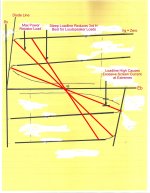
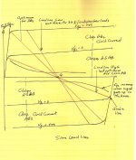
Unlike triodes, critical load for pentodes is important.
Ideally the loadline goes up into the knee of the pentode curve at G1 = Zero. But the location of the knee is dependent on the G2 voltage.
If the load impedance is set too high the loadline will drive the pentode screens into a high dissipation region as the signal increases.
Good design usually sets the loadline to lower impedance than optimum to account for a loudspeaker load with its resonances peaks.
And here are some examples of loadlines from my work.
All of this has a definite effect on the resulting D%. It spite of what some audiophool might claim.
BTW, I use Cookes Variable Constant as a starting point. 😀
😱
Attachments


I thought somebody would have picked up the ball by now & run with it.
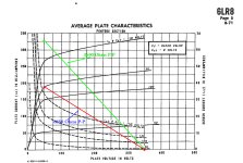
The OP has OPTs of 6.6K P-P & some 6LR8s. He will grow his own PSs. What to do?
Here is the 6LR8 plate family of curves with G2 as the variable.
There are two loadlines plotted & the results given for the P=P impedance result.
Easy to see why selecting the correct combination of plate & screen voltage is critical. 👍
Attachments
Well yeah - I just ran the numbers, and 20W (plus a little extra) is still available with the 6k6 transformer at 350V B+ . The screen current is peaking up, but I have efficient speakers currently driven to satisfactory levels by a Class A solid state amp with ~20W output capability. If I go up to 400V B+ and dial down the screen voltage a bit, it looks like I'll have more room to maneuver. Since I'm rolling the voltages on the DC-DC converter, that's not a big issue.
For the 6K6 load the screens need to run with 110-120V thru 1/2W, 1K resistors.
The amp performance & G2 heating would do better on a plane Jane resister load.
Where do you find these crazy ideas? 🙄
The extreme G2 current peaking up with G2 set much beyond 120V has absolutely nothing to do with your efficient speakers.The screen current is peaking up, but I have efficient speakers
The amp performance & G2 heating would do better on a plane Jane resister load.
Where do you find these crazy ideas? 🙄
I have appropriately sized screen resistors already in place on my layout, and can place the screen voltage any which way I please....
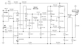
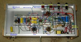
For the curious & lerkers here is a Cascode Differential Front end in a Class AB2 PP 6V6 Amp.cascode differential front end
Complete with a trick NFB connexion to the cascode upper grids. Gebuilt about 20 yrs ago.👍
Attachments
I'll be using folded cascade at the front end for level shifting and direct DC drive to the output stage. PNP HV TO-126 devices will be used for that duty. Again, the biggest question here will be how well the auto-balance circuit will function. Other than that, the design will be pretty humdrum.
I just received an octet of NOS Cinch PCB Novar sockets courtesy of RF Parts. Unlike the ones I got off Ebay, they fit nice and tight on the sample 6LR8s I have.
I've similar sweep tube quad project also w/ 12GT5's, which are cheap -$6. G2 specs at 160v. 440v B+ from rewound ChiFi trafo for the circuit below. Prolly use 2sc3150's in parallel w/ series zeners for needed voltage points from 370 VAC thru bridge. Wrestling w/ config of fixed bias & balance circuit design...The DC-DC converter I will use will supply +350V, +175V, and -50V for bias. I'm running the filaments on the 6LR8s directly in a series string from the 24V SMPS adapter that powers everything - a little bit of undervoltage on the filaments, but I'm willing to accept that. I'll use a simple series-pass regulator to drop the screen supply from 175V to 120V.
One pot for system bias voltage and one for balance between parallel banks? Or dedicated bias voltage pots for each parallel bank.
Seems there may be operational trade offs to each design
Jim
Attachments
- Home
- Amplifiers
- Tubes / Valves
- A Leap of Faith...