If you have a specific reason to get the output impedance lower, you could benefit from paralleling the two sections and doubling the current. I tried it early on and didn't think there was any benefit in my setup (10K input impedance for the crossover that this preamp drives, 2 meter cables). You hit diminishing returns quickly because of the cathode stopper resistor.
Crosstalk is below my measurement ability. Remember, the plates are at AC ground, so there's built-in shielding; this is a different case than when you have two voltage amplifiers in the same envelope. I suspect the limitation would be (source material aside!) the volume control.
Crosstalk is below my measurement ability. Remember, the plates are at AC ground, so there's built-in shielding; this is a different case than when you have two voltage amplifiers in the same envelope. I suspect the limitation would be (source material aside!) the volume control.
SY said:Crosstalk is below my measurement ability. Remember, the plates are at AC ground, so there's built-in shielding; this is a different case than when you have two voltage amplifiers in the same envelope. I suspect the limitation would be (source material aside!) the volume control.
Thanks a lot for the answer.
I was wondering how big is the crosstalk when you have voltage amplifiers. I am, rather slowly, preparing to make a phono stage. In general do people use different tubes for different channels and then try to match them or they use two triodes from the same valve for two channels in order to match the gain?
I mean channel separation of the turntavble is what, like 30dB, I suppose that two triodes inside the same valve have more...
I have never seen a balance resistor in phono stages, so I guess that the tube matching has to be rather tight?
Pred
pred said:I have never seen a balance resistor in phono stages, so I guess that the tube matching has to be rather tight?
No, we just ignore the problem and hope it will go away.
Seriously, just because two triodes are in one envelope doesn't mean they are likely to be matched. In fact, if you're concerned about matching phono stage gains, you're better off using individual valves and swapping them around until you get matched gains. Of course, this assumes that your cartridge has its outputs matched to within 1dB...
Note that because a cathode follower has 100% negative feedback, there will be negligible gain error between the channels even if the valves have measurably different mu.
Hi Stuart,
Since you've been more than helpful with tweaking my own preamplifier I've read though all pages of this trilogy with interest. There's a few questions still remaining though, so if you don't mind...
1) You use run-of-the-mill diodes to rectify the AC voltage for the anode supply of the ECC88. Hence the anode will receive it's voltage at the same time as the heater. Isn't it a better idea to have a delay between the two? Either by using a relay to switch on the anode voltage after the heater has warmed up, or use a tube rectifier, for example an EZ80/81?
2) Would a ring source for the CSS not allow for lower impedance and hence even better regulation of the CCS? Since you're using two transistors already this isn't a matter of adding parts, merely using them differently.
3) Are there any measurements available for the Mark 3 version with the servo? I noticed you've used RMAA before to get a proof of concept, and I'd love to see whether there's any improvements from the servo drive?
4) Anybody but you built this yet? I'd love to see some pictures if available.
Thanks and best regards,
Sander Sassen
http://www.hardwareanalysis.com
Originally posted by SSassen
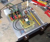
4) Anybody but you built this yet? I'd love to see some pictures if available.
Getting closer... 🙂
Attachments
Hence the anode will receive it's voltage at the same time as the heater. Isn't it a better idea to have a delay between the two? Either by using a relay to switch on the anode voltage after the heater has warmed up, or use a tube rectifier, for example an EZ80/81?
Delay is important for high B+, where cathode stripping can occur. The B+ here is 90V, which won't hurt a thing. My old preamp also used ECC88, albeit at even higher voltages, and I got about 15 years on the last set of tubes (which still seem to work fine).
Tube rectifiers are in every way inferior to solid state except for a few niche uses and sociological reasons.
Would a ring source for the CSS not allow for lower impedance and hence even better regulation of the CCS?
You want a current source to have as high an impedance as possible. A ring-of-two will probably work OK, but the cascode performs flawlessly and I've never had one oscillate on me.
Are there any measurements available for the Mark 3 version with the servo? I noticed you've used RMAA before to get a proof of concept, and I'd love to see whether there's any improvements from the servo drive?
The measurements I showed were for the servo version with the integrator biasing the ECC88 grid. The modified servo (i.e., using the servo to vary the ECC88 B+) ended up giving me no performance advantage, measured exactly the same, below residual. So it never got built into a nice box. It's novel, but hard-*** that I am, I expect novelty to increase performance and am happy to toss it aside if it doesn't.
Excellent news- I owe boards to a couple of people (especially Broskie!), so I'd sure love to get them proven out and production ones ordered.
And Mrs. Y is anxious for me to do a nice build so I can get that baboon-butt-ugly one out of the living room.
And Mrs. Y is anxious for me to do a nice build so I can get that baboon-butt-ugly one out of the living room.
Pinkmouse,
Excellent! How about a bit more detail? Got any layout files you might be willing to share? I'd also love to hear whether the Jensen transformers are worth every penny, or I could safely go with one of the alternatives?
Best regards,
Sander Sassen
http://www.hardwareanalysis.com
Excellent! How about a bit more detail? Got any layout files you might be willing to share? I'd also love to hear whether the Jensen transformers are worth every penny, or I could safely go with one of the alternatives?
Best regards,
Sander Sassen
http://www.hardwareanalysis.com
Thanks SY,
That answers my questions. I guess all I now need for a bit of gain is a 12B4 as a mu-follower and I'm all set I guess.
Best regards,
Sander Sassen
http://www.hardwareanalysis.com
That answers my questions. I guess all I now need for a bit of gain is a 12B4 as a mu-follower and I'm all set I guess.
Best regards,
Sander Sassen
http://www.hardwareanalysis.com
There are a few odd layouts dotted around the forum,(here's one for instance), but the current ones are really down to SY to check first, and then give permission to publish. However, if he is making up a batch of boards he might well have spare proper ones to sell on. 😉
The Jensen transformers are excellent, but so far, I've found the Cinemags to be just as good with somewhat lower pricing. You can also do a 1:2 step-up if you want 6dB of gain.
Hi,
Sorry to say so but that's not quite correct.
Cathode stripping isn't exactly relative to the B+ but is caused by thermal cycling where excessive amounts of current are tried to be drawn from a cathode that just can't deliver it due to its thermal condition. I.e. not yet hot enough or already cooling down.
Inferior for anything but audio perhaps?
Unless we're using Schottky type diodes the switching of typical rectifier diodes is going to creap into the audio.
In conjunction with tubed electronics tube rectumfriers have their disadvantages but those are mainly of an econonical nature, heater requirements and limited current output. The latter may well be an advantage, occasionally saving a runaway tube but I digress........
See former Philips Engineer J.H.van de Weijer for more detail.(Or most of the Philips Professional Tube Electronic books for that matter.)
With regard to cathode stripping the slow turn-on characteristic of the tube rectifier may also help to prevent cathode stripping. Respecting the manufacturer's stated maximimum grid resistance is also helpful here..........
That all of this is not really necessary for this type of application may well be true but it still doesn't make it correct.
Cheers, 😉
Delay is important for high B+, where cathode stripping can occur. The B+ here is 90V, which won't hurt a thing. My old preamp also used ECC88, albeit at even higher voltages, and I got about 15 years on the last set of tubes (which still seem to work fine).
Sorry to say so but that's not quite correct.
Cathode stripping isn't exactly relative to the B+ but is caused by thermal cycling where excessive amounts of current are tried to be drawn from a cathode that just can't deliver it due to its thermal condition. I.e. not yet hot enough or already cooling down.
Tube rectifiers are in every way inferior to solid state except for a few niche uses and sociological reasons.
Inferior for anything but audio perhaps?
Unless we're using Schottky type diodes the switching of typical rectifier diodes is going to creap into the audio.
In conjunction with tubed electronics tube rectumfriers have their disadvantages but those are mainly of an econonical nature, heater requirements and limited current output. The latter may well be an advantage, occasionally saving a runaway tube but I digress........
See former Philips Engineer J.H.van de Weijer for more detail.(Or most of the Philips Professional Tube Electronic books for that matter.)
With regard to cathode stripping the slow turn-on characteristic of the tube rectifier may also help to prevent cathode stripping. Respecting the manufacturer's stated maximimum grid resistance is also helpful here..........
That all of this is not really necessary for this type of application may well be true but it still doesn't make it correct.
Cheers, 😉
I've done everything I could to observe those switching spikes in the audio and couldn't. If I probe inside the rectifier/transformer/first filter cap loop, I can see them, but not at the output of the supply. Admittedly, I did a decent job of grounding, and if that's not done, rectifiers can be an issue.
Sorry, I don't follow your argument about current draw and cold cathodes at all. At cold startup, it will take one mighty field to strip out electrons and "try" to get current flowing. 900V anode-to-cathode, sure, it's possible, maybe. 90V? Not a chance. I'm open to actual evidence to the contrary.
Sorry, I don't follow your argument about current draw and cold cathodes at all. At cold startup, it will take one mighty field to strip out electrons and "try" to get current flowing. 900V anode-to-cathode, sure, it's possible, maybe. 90V? Not a chance. I'm open to actual evidence to the contrary.
Hi,
Well those little diodes also cause transient spikes at the other end of the powerxformer causing dirty AC supply lines downstream.
While you may have taken care of that PS you built yourself there's no guarantee someone else has done the same.......
It's not because the problem is downscaled that it's suddenly gone or, is it?
It's not current draw alone either it's also remaining charges present when a unit is sequenced.
Talk to any electric guitar player and his repair shop and they'll tell you the gross of the tubes getting replaced didn't just die from old age but from prematurely exhausted cathodes. How could this happen?
A tube rectifier or properly sequenced delay system won't take away all of the problems but it sure helps. So does educating those guitar players...........
Anyway, I'll leave you to the circuit at hand.😉
Ciao, 😎
I've done everything I could to observe those switching spikes in the audio and couldn't. If I probe inside the rectifier/transformer/first filter cap loop, I can see them, but not at the output of the supply. Admittedly, I did a decent job of grounding, and if that's not done, rectifiers can be an issue.
Well those little diodes also cause transient spikes at the other end of the powerxformer causing dirty AC supply lines downstream.
While you may have taken care of that PS you built yourself there's no guarantee someone else has done the same.......
Sorry, I don't follow your argument about current draw and cold cathodes at all. At cold startup, it will take one mighty field to strip out electrons and "try" to get current flowing. 900V anode-to-cathode, sure, it's possible, maybe. 90V? Not a chance. I'm open to actual evidence to the contrary.
It's not because the problem is downscaled that it's suddenly gone or, is it?
It's not current draw alone either it's also remaining charges present when a unit is sequenced.
Talk to any electric guitar player and his repair shop and they'll tell you the gross of the tubes getting replaced didn't just die from old age but from prematurely exhausted cathodes. How could this happen?
A tube rectifier or properly sequenced delay system won't take away all of the problems but it sure helps. So does educating those guitar players...........
Anyway, I'll leave you to the circuit at hand.😉
Ciao, 😎
It's not because the problem is downscaled that it's suddenly gone or, is it?
Pretty much, yes. If the field does not cause the electron energy to exceed the work function of the cathode coating, nothing will happen.
Re: the grounding issue, that's why pinkmouse is designing a board. Point to point ought to be left to us veterans.😀
A couple of quick questions. I apologize if these have been answered elsewhere.
What happened to the 1M resistor from input to ground in the version of the schematic in this thread?
Any thought on using some Edcor transformers (http://www.edcorusa.com/transformers/wsm/wsm10k-10k.htm) for a first build at least until I get something working?
For the 470R trimmer, how does one go about setting this and will it change with different tubes?
-d
If you mean the grid leak resistor, that's replaced by the 10M resistor connected to the output of the servo.
The Edcors are rumored to be good, but I haven't tried them yet. For a first build, they'll certainly be more than good enough; if you're unhappy with the bass, you can always upgrade to Cinemag or Jensen later on.
CCS adjustment was detailed in Part II. Basically, you connect them to a test resistor and set for the desired operating current, then remove the test resistor and hook the adjusted CCS to the cathodes. The beauty of CCS is that they'll set the desired current independent of which tube you put in the socket (within reason!). Set and forget.
Okay, one more. Any reason for the pot to be 100K, or was that just the part on hand. Could it be 50K pot with a 12K5 resistor, or a 10K pot and no resistor?
Yes, as long as the load on the transformer is 10k, you're good to go. The 100k was a pot that I just happened to have, so I paralleled a resistor with it. A 10k pot wouldn't need one.
- Status
- Not open for further replies.
- Home
- Amplifiers
- Tubes / Valves
- A Heretical Unity Gain Line Stage part III