I don't know; I'm not set up for RF measurement. In practice, I have had zero RFI problems even from nearby TVs, computers, and cell-phones; the comparative noise floor between loop-back and preamp that I showed in one of the graphs is pretty impressive, so any RF noise in that bad test environment isn't causing an issue in the audio band.
It's a pretty standard high end transformer in broadcast studios, so it probably does well.
It's a pretty standard high end transformer in broadcast studios, so it probably does well.
You must not carry a BlackBerry. I yet to run across an amplified speaker, for example, that doesn't sing in delight at one's approach.
RF immunity is strongly dependent on the external ground references. I once wired out a studio on the 25th floor of a print building two miles into the main lobes of a pair of AM stations. All the 'standard' central grounding practices turned every microphone into a tuner.
RF immunity is strongly dependent on the external ground references. I once wired out a studio on the 25th floor of a print building two miles into the main lobes of a pair of AM stations. All the 'standard' central grounding practices turned every microphone into a tuner.
Last edited:
You must not carry a BlackBerry.
You're right, I don't. Being too connected is not good for my mental health.😀
Wow. If a little blackberry can do that imagine how much interference you could cause with a watermelon.
I'm a little lost. Are these PCB's available for purchase from someone/where? Is there a way for me to have someone local print them from plans for me?
I too would be interested in a pcb set if still available ! please pm me with the details if still available ect... Thank-you
I've read somewhat in this thread. Good stuff but beyond my capacity to cope intellectually. Anybody want to talk theology? I might be able to keep up. That is, after all what attracted me to the thread.
Anyway, I'm into CCS a little and still don't fully understand source follower mosfets but maybe in time.
Is there a thread for a "not so "heretical" line stage suitable for Baby Huey? That poor little tube is soooooo lonely amongst all that silicon.
Anyway, I'm into CCS a little and still don't fully understand source follower mosfets but maybe in time.
Is there a thread for a "not so "heretical" line stage suitable for Baby Huey? That poor little tube is soooooo lonely amongst all that silicon.
Actually, this should work fine with Baby Huey. That amp has enough gain not to need the ministrations of an amplifying line stage.
Can't help you with theological discussions- they get me nauseated.😀
Can't help you with theological discussions- they get me nauseated.😀
The Manachaeists weren't responsible for the RF problems in that building I'll have you know. I'll agree though that they were a lot of trouble. I'll bet you spent a good deal of time making chokes eh? Grounded screen in the walls helps. I somehow doubt you ever got it all. That's about the worst environment for a studio I can think of.You must not carry a BlackBerry. I yet to run across an amplified speaker, for example, that doesn't sing in delight at one's approach.
RF immunity is strongly dependent on the external ground references. I once wired out a studio on the 25th floor of a print building two miles into the main lobes of a pair of AM stations. All the 'standard' central grounding practices turned every microphone into a tuner.
Even more OT. There used to be an over the horizon scanning defense radar system in San Jose California that would inject a bzzzzzzt of about .58 seconds in duration with every turn of the antenna, into every audio device, telephone, movie theatre sound track etc etc for hundreds of miles around back in my salad days. You had to cap and coil everything, (i forget the values) but it never completely disappeared. The antenna sat on Mount Umanum. Kinda appropriately named actually. They took the dish down but the building is still there I think. I think I heard the dish was about 300 feet across. I've always wondered what the tubes were that pushed that signal. Probably still classified.
There are some Jensen JT11 P1 transformers on that auction site for $50/pc. No relation to the seller, other than I'm waiting for delivery of a pair.
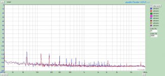
I am curious about the measured noise performance of this preamp. Unfortunately the plots seem to be no longer available but if it is the normal spectrum type graph you get with RMAA and the noise in rumbling along the bottom below -100dB then that does NOT mean the noise is below -100dB. That plot shows the noise per root unit bandwidth so you get the actual output noise level you need to integrate it over the 20KHz audio bandwidth which effectively means adding about 43dB to the measured figure. So if the plot shows noise at -120dB then the rms noise is only -77dB which is nowhere near the spec.
Cheers
Ian
Cheers
Ian
You're right, that doesn't, but a wide range AC voltage measurement (I used an HP3581A) does, as does RMAA in one of its reporting functions. Using a more recent soundcard/software combo, a build with the power transformers and raw supply in the same case as the signal circuits, no particular shielding, gave a noise floor in the -140 to -150dBV range, with the spray of noise pickup from the transformers reaching -120dBV. I could probably eliminate that with some effort, but the payoff is too small to prioritize that. The channel with the lower 60Hz was located on a card about 5" further from the transformers.
Attachments
What does the HP3581A show as total noise? The measurement was in mV, I suppose? (My HP works that way)
Microvolts, yes, with several different bandwidths. Very convenient for plotting noise voltage density. Don't have the data handy since that's "write it in the lab notebook" stuff and we're surrounded by boxes at the moment. 😀
Cool, let us know what you have when you unearth the notebook. My old HP 8903B at work does AC RMS voltages like that with several different bandwidths and A-weighting. Very handy.
You can back into it from the spectra and get a pretty close answer by approximating the LF noise floor at -145dBV and the HF noise floor by -150dBV. Much of the limitation is in the soundcard and the HP- ECC88 types are darn quiet tubes.
How do you figure total noise from the floor? What's the formula? Normally I just let ARTA tell me.
What does the HP3581A show as total noise? The measurement was in mV, I suppose? (My HP works that way)
This is strange because my HP3581A does nothing of the sort. Its essentially a spectrum analyser and does not measure wideband noise - or is there some function on it I am not aware of?
Cheers
Ian
This is strange because my HP3581A does nothing of the sort. Its essentially a spectrum analyser and does not measure wideband noise - or is there some function on it I am not aware of?
It has a frequency control knob and digital readout, where you can set the center frequency and get the noise for that band, then increase the frequency to the next band to get the noise voltage there, and so on. If you divide the noise voltage by the bandwidth (selectable by another knob), that gives you the voltage noise density for that frequency band. You can easily make a plot of en vs. f, and at very high resolution if you have the patience. Perhaps some time reading the manual may help; it's an incredibly versatile instrument and the use of it to measure noise is explained in there. I think the BAMA site has the manual for download if you don't have it.
The correlation between noise measured with the HP and the noise from RMAA is quite good.
edit: You can also do this with the sweep function, but since I don't have a pen plotter, I haven't done it that way.
- Status
- Not open for further replies.
- Home
- Amplifiers
- Tubes / Valves
- A Heretical Unity Gain Line Stage part III