MOAR POWERRRRR!!!
😀 😀 😀

Ok, easy.
Build a second F4, run them both as mono from a balanced preamp that can output 35vrms.
That's 100WPC monoblocks. This configuration is shown in the F4 manual.
😀 😀 😀
Ok, easy.
Build a second F4, run them both as mono from a balanced preamp that can output 35vrms.
That's 100WPC monoblocks. This configuration is shown in the F4 manual.
Can't a guy want more power for no reason at all? Cheez! 🙂
If you wanted to stay with the original design and not go the balanced route and let's say you wanted a full 25W with better sound quality at those peaks, you could go with 30V to 32V rails.Increasing power is as simple as going balanced (4 times more power)
Alternatively you could increase the rail voltages, but not sure whether the jfets are happy swinging voltages greater than 24V at the gate. You could take the jfets out if it were necessary.
I guess even if you never exceeded 24V signal peaks there is some benefit having some additional voltage drain to source, that is assuming you actually were swinging 24V peaks in the first place.
That would be worthwhile if you were using the full 25W.
For me personally I prefer an amp that sounds dynamic and powerful at normal listening levels.
To do that requires a different approach than just adding more power.
Last edited:
Hi all. As those of you following the "F4 Power Amplifier" thread will know, Nelson recommends Harris IRFP9240 parts for the P-channel mosfets as they show reduced distortion compared to the 9240s from other manufacturers (see:
https://www.diyaudio.com/forums/pass-labs/97540-f4-power-amplifier-463.html#post6311086). Based on this recommendation, I purchased and matched some Harris parts for a new premium build of the F4.
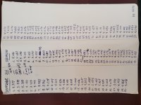
Due to a large minimum order quantity at Rochester Electronics, I currently have 34 extra if anyone would like a matched set (50 currently under reservation). If so, please PM me. They have been matched at a constant temperature of 50C and at the F4 operating characteristics of 22V and .42A. I'm selling at cost which is around $3 per mosfet + shipping.
Pictures of the testing rig below.
https://www.diyaudio.com/forums/pass-labs/97540-f4-power-amplifier-463.html#post6311086). Based on this recommendation, I purchased and matched some Harris parts for a new premium build of the F4.
Due to a large minimum order quantity at Rochester Electronics, I currently have 34 extra if anyone would like a matched set (50 currently under reservation). If so, please PM me. They have been matched at a constant temperature of 50C and at the F4 operating characteristics of 22V and .42A. I'm selling at cost which is around $3 per mosfet + shipping.
Pictures of the testing rig below.
Attachments


Good job.
You could add a dollar to the mosfet price and I don't think anyone would complain.
You could add a dollar to the mosfet price and I don't think anyone would complain.
Hi folks, everything's taken... I'll be asking for mailing addresses via pm and will ship out by the end of next week. Hope they sound great...
Yes, especially if you are drilling aluminum vs steel.
There may also be an issue with high current amps in steel chassis, although I'm not certain that it applies.
People have said high current in steel is ok.
There may also be an issue with high current amps in steel chassis, although I'm not certain that it applies.
People have said high current in steel is ok.
Steel works very well. Aluminum is easier to drill, as you mention. Aluminum looks a little better.
I have both kinds of chassis, I find I prefer Aluminum for power amps and Steel for line-level.
I have both kinds of chassis, I find I prefer Aluminum for power amps and Steel for line-level.
Morgan Jones recommends aluminum over steel for EMI rejection. I have never seen a difference. Like has been said, it's easier to work with.
Another piece of advice for any reading this is to skip the perforated base plate and learn to use inexpensive speed taps and place your components exactly where you want them in the chassis in a matter of minutes.
1. Lay all empty pcbs over the aluminum substrate. Once you have the exact layout you
want, blue tape each pcb in place.
2. Mark with a punch or white marker.
3. Pre-drill each hole with a 2.5mm bit (for 3mm fasteners).
4. Speed tap, using simply 3 in 1 or cutting oil with electric drill.
Cheers,
Greg
Due to a miscommunication, I have 6 matched Harris 9240s left (two matched trios). Anyone want them?
Hi all. As those of you following the "F4 Power Amplifier" thread will know, Nelson recommends Harris IRFP9240 parts for the P-channel mosfets as they show reduced distortion compared to the 9240s from other manufacturers (see:
https://www.diyaudio.com/forums/pass-labs/97540-f4-power-amplifier-463.html#post6311086). Based on this recommendation, I purchased and matched some Harris parts for a new premium build of the F4.
Due to a large minimum order quantity at Rochester Electronics, I currently have 34 extra if anyone would like a matched set (50 currently under reservation). If so, please PM me. They have been matched at a constant temperature of 50C and at the F4 operating characteristics of 22V and .42A. I'm selling at cost which is around $3 per mosfet + shipping.
Pictures of the testing rig below.
Dear future builders.
As you can read about over in the "f4 power amplifier thread" (see ~p485), I would recommend replacing the bl431 part listed in the bom with NCP431ACLPRAG (Mouser Part Page).
The bl431 is a shunt voltage regulator on the f4 input buffer and requires a minimum current of 1mA to operate appropriately. Even in standard builds this minimum may not be met. The ncp431 has the same output characteristics, but a minimum operating current of 40uA.
It's an easy drop in replacement and ensures that you will be hearing the amp as intended.
Note that the in most cases, the amp will still operate with the standard bl431 out of spec, you just won't be hearing all it can offer. If you would like to measure your f4 to see if this part is receiving enough current, see this post: F4 power amplifier.
Last edited:

- Home
- Amplifiers
- Pass Labs
- A guide to building the Pass F4 amplifier