Well done, satisfying when they get sorted isn't it.
Indeed! For a moment I was afraid that I had fried the outputs but the light bulb did its work and saved the day!! 🙂
Great work.Sucess!! Changed the mosfet's position and everything started up correctly!!
I have 250mV running through the mosftets for about 0.53A of bias current per each one!
So I have 27W of nice class A power feeding my ~6ohm speakers!!
Now off to finish the BA3 preamp!! 🙂 🙂
My turn for debugging help, please. 🙂
I'm testing my first F4 channel this evening.
The PSU works fine. I've adjusted V+/V- to 23v/-23v using my variac (at 110v ac).
Bringing up the channel my light bulb tester does not go on, so no short.
But not current either -- there is no bias across the 0.47R bias resistors. Kind of like this guy experienced:
http://www.diyaudio.com/forums/pass-labs/234355-guide-building-pass-f4-amplifier-70.html#post4389748
Per Zenmod's instructions there, I measured "voltage between opposite mosfet gates". Between Q3 and Q6 gates I measure 6.1v.
Across the TL431 outside pins I measure about 3.5 volts.
Cheers.
Last edited:
If you're measuring voltage of 6.1V between gate pin of N mosfet to gate pin P mosfet.
It's simple you need more voltage at the gates to turn them on.
It's simple you need more voltage at the gates to turn them on.
It's simple you need more voltage at the gates to turn them on.
Those poor gates. How can I help them?
Using the circuit diagram in post 1 of this thread, what values do you have for R8, R9 and what is P1 set at?
Last edited:
Basically the total resistance of R9 and P1 needs to be reduced.
V is approximately equal to 2.5 x ( R8 + (R9 + P1)/(R9 + P1)). Simplified to 2.5 x (1 + (R8/(R9 +P1))).
Eg 2.5 x (1 + (20k/(8k + 2k)) = 7.5V
V is approximately equal to 2.5 x ( R8 + (R9 + P1)/(R9 + P1)). Simplified to 2.5 x (1 + (R8/(R9 +P1))).
Eg 2.5 x (1 + (20k/(8k + 2k)) = 7.5V
Last edited:
Hey PicoDude, thanks for the help!
I increased P1 all the way (fully turned to the right) and the gates are somewhat happier -- 0.050 volts across bias resistors. Between N to P is now 7.56v. The light bulb tester with 50w bulb is glowing faintly so that shows current is flowing too.
R8 is 22k
R9 is 10k
I have a 5k R9 as backup per 6L6's build instructions on the first page of this thread so I'll try that. Unless you recommend trying something else...
Last edited:
Changed R9 to 5k.
Now can get up to 0.062 volts across bias resistor with P1 maxed clockwise (lowest R). Between N to P is now 7.75v.
But I rechecked V+/V- and it's, gulp, 13v/-13v. The light bulb tester is dimly on. In retrospect, was this light bulb on a clue that I am pulling current wrongly somewhere else in the circuit?
back with bias pots , remove bulb tester , repeat procedure
use 2 DVMs , one for Iq ( voltage across Rs ) , another one for DC offset
use 2 DVMs , one for Iq ( voltage across Rs ) , another one for DC offset
Answered my own question there...
Took out the light bulb tester and all is well. Using two meters I was able to easily set the cold MOSFET bias to 0.130 and null out DC offset.
Took out the light bulb tester and all is well. Using two meters I was able to easily set the cold MOSFET bias to 0.130 and null out DC offset.


Thanks guys,
I'm moving cautiously here because this is my first Class A SS amp, still learning the bring up procedures, and I don't prefer rework. It's all good practice so I don't smoke VFETs in the next build. 🙂
Still gotta test whether I have audio on the first channel, and then test the second channel.
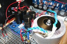
I'll post a review with some pics of my build if/when it's all working. 😉
I'm moving cautiously here because this is my first Class A SS amp, still learning the bring up procedures, and I don't prefer rework. It's all good practice so I don't smoke VFETs in the next build. 🙂
Still gotta test whether I have audio on the first channel, and then test the second channel.
I'll post a review with some pics of my build if/when it's all working. 😉
Last edited:
Yes, audio on the first channel works. And the second channel came up without incident. So I'm listening to stereo now on the F4 with my test speakers. Yah!
Per 6L6's instructions, I set bias cold to 0.130v. After an hour or so, the bias is up to 0.150v on both channels. The next instructions are to "trim" bias to 0.200v. Does this make sense that the bias didn't change much in an hour? Should I just go ahead and up it to 0.200v and readjust dc offset?
Per 6L6's instructions, I set bias cold to 0.130v. After an hour or so, the bias is up to 0.150v on both channels. The next instructions are to "trim" bias to 0.200v. Does this make sense that the bias didn't change much in an hour? Should I just go ahead and up it to 0.200v and readjust dc offset?
Attachments
Yes, the bias will shift as the components heat up so best practice is to put the cover on the enclosure and let it run for an hour or so, then re adjust the bias setting. Don't forget to trim the DC offset anytime you change the bias.
Thanks mcandmar. I'm very biased now. 🙂
I've moved the F4 amp to my main system on the horns (I bi-amp with a First Watt B4). Will post about sound quality later.
I was expecting to have to move to the 6db mode of my preamp from the 0db buffer mode. But no need at this point, it seems. I'm running the volume dial at 11:00 o'clock to 1 pm. Which is kind of amusing since the amp itself has no gain, of course.
My DAC puts out 2v, but I am pre-processing with Acourate DSP in software which knocks about 7db off the signal. So it isn't even a 2v max signal out.
My current amps for the horns, gainclone monoblocks and 300b, have 30db of gain so this is a big improvement just from that standpoint, and was a main thing I was looking to improve.
The amp is the quietest I've experienced on horns - just a touch of noise with the ear in the horn (and maybe that is from the tube preamp or other components).
I want to try the amp on my bass/lower midrange channel, but I'll need to finish the K&K 4P1L gain stage I'm working on first.
Last edited:
- Home
- Amplifiers
- Pass Labs
- A guide to building the Pass F4 amplifier