What should change if I want to increase the number of output devices to say 4 or 5 pairs? I have really inefficient (86dB/1W/1m) 4R speakers. I could bridge two channels for a total of 12 output devices, but my case won't be able to handle the heat of a stereo amp (and I don't have the budget for monoblocks) . I have a modushop 5U 400 chassis. Would the jfet input buffer of a single channel be able to drive 4 or 5 pairs of output devices? Thanks
add more output devices (along with source resistors), but set sum Iq on regular value
that way you can expect more Cojones in current peaks, while heat will stay the same
buffers will do, no worry
though - will you hear difference, only you can tell, afterwards
that way you can expect more Cojones in current peaks, while heat will stay the same
buffers will do, no worry
though - will you hear difference, only you can tell, afterwards
Thanks ZM - I was actually thinking of more output devices at the recommended bias settings (ie. higher sum Iq) for more heat and more overall power. My modushop 5U 400 chassis should be able to dissipate 270-300W of heat, which should work for 5 pairs of output devices but may not be enough to fully duplicate each channel. Any idea why for higher power, Papa Nelson recommends a parallel mono arrangement (so parallel input buffers and 6 output pairs) rather than simply adding extra output devices (as for the ba-2)?

Thanks ZM - I was actually thinking of more output devices at the recommended bias settings (ie. higher sum Iq) for more heat and more overall power. My modushop 5U 400 chassis should be able to dissipate 270-300W of heat, which should work for 5 pairs of output devices but may not be enough to fully duplicate each channel. Any idea why for higher power, Papa Nelson recommends a parallel mono arrangement (so parallel input buffers and 6 output pairs) rather than simply adding extra output devices (as for the ba-2)?
you can go up with Iq per device, up to 35W (for 240/9240), if you keep them cool
that's way more than heatsink of 5U/400 can cope with
as Jim sez, - crank it, keeping a palm on heatsink
With the 5U chassis i think i got to around 225mv @55c, and even with rather inefficient speakers i never found it wanting for output power. Just built it and see..
Where is the best place to connect the XLR ground pin to the circuit? Power supply neutral or back to one of the circuit grounds?
XLR pin 1 goes to chassis, by the book
if you connect it to same place as RCA GND (pcb input GND point) and there is no hum, that's also by the (little smaller) book
if you connect it to same place as RCA GND (pcb input GND point) and there is no hum, that's also by the (little smaller) book
I've got both here, an Aleph 4 and an Aleph J, they are both really impressive amplifiers.
My impression is that the Aleph J is actually better at normal listening levels.
The Aleph 4 seems to sound a bit harsh at lower level but comes into it's own when being driven hard.
The difference in volume between the two is hardly noticeable at full volume.
I suppose it does come down to your speakers and source in the end.
The Aleph 4 is built as a dual mono-block, the Aleph J just has a single monster PSU.
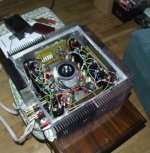
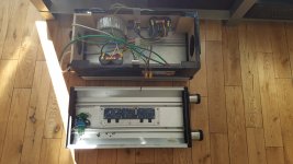
Attachments
Last edited:
The F4, being a gainless current follower, can’t really be thought of in a vacuum - the device in front of it Is being passed through with as little colorization and editorial impact as possible. I.E., the F4 sounds like the preamp driving it...
That said, I really like both.
That said, I really like both.


i gents. I hope you can help me.
Both my f4 boards are giving me problems.
I can't get more than 90mV and I have around ten volts at the speaker outputs.
Change R8 from 22.1K to 27.4K should give you more room for biasing.
Where (which source resistor) are you measuring the 90mV? My guess is that the
mosfets on one polarity are on and those on the other are still off.
Where (which source resistor) are you measuring the 90mV? My guess is that the
mosfets on one polarity are on and those on the other are still off.
Hi Dennis. Thank you for the quick reply.
I checked on a few source resistors, I didn't note if p or n.
Why would one polarity be off?
I checked on a few source resistors, I didn't note if p or n.
Why would one polarity be off?
Hi Dennis. Thank you for the quick reply.
I checked on a few source resistors, I didn't note if p or n.
Why would one polarity be off?
I had exactly the same bias until I changed R8. Now I can crank it to beyond 400mV 😀, which is of course not necessary. Papa states in the service manual that the target bias is 200mV (cold @130mV). I run mine at 300mV, where it’s very smooth, warm, and open sounding after 1 hour of operation.
Cheers,
Greg
Dennis and Greg. Many thanks for the pointers. I will change the resistors today.
Cheers guys,
Billy
Cheers guys,
Billy
- Home
- Amplifiers
- Pass Labs
- A guide to building the Pass F4 amplifier