LED is not critical for the F4 as it's only used to indicate that it's on.
Blue LEDs work nicely and if it's too bright, you can increase the value of the resistor just before it to bring the glow down.
Blue LEDs work nicely and if it's too bright, you can increase the value of the resistor just before it to bring the glow down.
and ....... Papa is using diffuse blue LEDs
bright ones are pain even with 1mA
rule of thumb/thumb of rule - 1K per rail volt and you're good ; with clear blue leds you can even double it
bright ones are pain even with 1mA
rule of thumb/thumb of rule - 1K per rail volt and you're good ; with clear blue leds you can even double it
Thanks guys. Most helpful. I'm still at the beginning of the learning curve.
Also helps make sense looking at the schematic
Cheers
Also helps make sense looking at the schematic
Cheers
F4
Hello again,
I had to leave my F4 unfinished before Xmas as a few life problems arose, as ever **** happens in threes.
Recently I have had a little time to try and find out where the F4 problem lies and am struggling to find a solution.
Here is where I am at the moment.
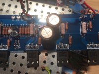
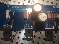
Without the boards connected the PSU LEDs light up with a 1.25 fuse in place.
With the right-hand channel connected both the PSU and LED on the board come on.
Left-hand board connected results in a blown fuse.
Things I have tried so far.
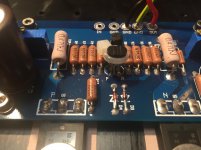
1, Replaced all insulation pads beneath MOSFETs, all legs of MOSFETs tested to the heatsink have similar readings.
2, Tested without RCA or banana sockets connected.
3, Thoroughly inspected both boards side by side to ensure they are identical.
4, Where solder is not visible on both sides of the board, ie under caps etc these have been removed and resoldered.
5, Swapped rectifier blocks over to eliminate a not visible fault.
6, Upped the fuse size which fried R16 to 21 these have been replaced.
Is it possible to have a faulty component? Does anyone have any other suggestions of where I could look?
Thanks for your help.
Hello again,
I had to leave my F4 unfinished before Xmas as a few life problems arose, as ever **** happens in threes.
Recently I have had a little time to try and find out where the F4 problem lies and am struggling to find a solution.
Here is where I am at the moment.
Without the boards connected the PSU LEDs light up with a 1.25 fuse in place.
With the right-hand channel connected both the PSU and LED on the board come on.
Left-hand board connected results in a blown fuse.
Things I have tried so far.
1, Replaced all insulation pads beneath MOSFETs, all legs of MOSFETs tested to the heatsink have similar readings.
2, Tested without RCA or banana sockets connected.
3, Thoroughly inspected both boards side by side to ensure they are identical.
4, Where solder is not visible on both sides of the board, ie under caps etc these have been removed and resoldered.
5, Swapped rectifier blocks over to eliminate a not visible fault.
6, Upped the fuse size which fried R16 to 21 these have been replaced.
Is it possible to have a faulty component? Does anyone have any other suggestions of where I could look?
Thanks for your help.
Attachments
Blimey, I didn't realise that at all .
So i'll just swap the three on the left over to the right and visa versa.
Thanks for spotting that.
So i'll just swap the three on the left over to the right and visa versa.
Thanks for spotting that.
Ok, all up and running, I would just like to check if this is the correct resistor to order for R9 as I can only adjust up to 110 mv so need to swap resistors for a better range of adjustment .PTF654K7500AZEK Vishay / Dale | Mouser France
Thanks.
Thanks.
That value should work though using a 0.05%/5ppm resistor may be overkill.
Here's an RN60 4.75K, which should match the rest of your resistors:
RN60C4751FRE6 Vishay / Dale | Mouser Canada
Don't forget to reset P1 (5K pot) to maximal value before startup after changing
the resistor.
Here's an RN60 4.75K, which should match the rest of your resistors:
RN60C4751FRE6 Vishay / Dale | Mouser Canada
Don't forget to reset P1 (5K pot) to maximal value before startup after changing
the resistor.
I had a closer look and it seems you have 22.1K for R8? If so, I suggest
changing that to 27.4K (as in the latest schematics) and leave R9 at 10K.
If you change R9 to 4.75K then even with max value of P1, you will have significant
current flow (since you already have 110mV across 0.47 in your current setup).
Sorry for the confusion.
changing that to 27.4K (as in the latest schematics) and leave R9 at 10K.
If you change R9 to 4.75K then even with max value of P1, you will have significant
current flow (since you already have 110mV across 0.47 in your current setup).
Sorry for the confusion.
No problem, would this be the correct one?CMF6027K400FKEK Vishay / Dale | Mouser France
One other Quick question regarding max value on the Bourns pot, it seems to turn endlessly should I just do say 10 clockwise turns to be sure it is at max value?
One other Quick question regarding max value on the Bourns pot, it seems to turn endlessly should I just do say 10 clockwise turns to be sure it is at max value?
Last edited:
That works.
Or the RN60 version (in case you want all your resistors to look the same 🙂 ):
RN60D27R4FRE6 Vishay / Dale | Mouser Canada
You should hear a slight click when you are at the end of the pot's adjustment range.
But that doesn't tell you whether you're at max or min value.
In your case you know that you run out of adjustment room for bias. That occurs
when P1 is at min value. So turn in the opposite direction so that the bias
decreases and when you hear the click, you should then be at maximal value.
If I have understood the max value of the Bourns pot equals minimum bias which is where I should be before next switch on?
Thanks.
Thanks.
I have now changed R8 for the 27.4 resistors and left everything else as it was. The born pots were wound anticlockwise to a very low reading before changing both R8s, at switch on the LEDs all light up but I am not getting any heat from the heat sinks and the 0.47 test won't budge from zero no matter how many clockwise turns of the pot P1. At the moment I have only left it on for a few minutes as I think something may be wrong.
I have tried several different 0.47 resistors.
Have I missed something?
I have tried several different 0.47 resistors.
Have I missed something?
R8?
which exact schm, to avoid mix-ups?
I'm not finding a place for 27.4 Ohms resistor anywhere in circuit ...... or it was a typo- you meant 24.7K?
edit: what max voltage you are getting across TL431 (A-K) ?
which exact schm, to avoid mix-ups?
I'm not finding a place for 27.4 Ohms resistor anywhere in circuit ...... or it was a typo- you meant 24.7K?
edit: what max voltage you are getting across TL431 (A-K) ?
Last edited:
- Home
- Amplifiers
- Pass Labs
- A guide to building the Pass F4 amplifier