Yes, the dynamic THD is very hard to calibrate
 The parasitical capacitance of the switch will greatly decrease dynamic in high frequence, especially when the large step occur, which is the most troublesome thing I confront with. The only thing we can do is expect the setting time is shorter, shorter...
But reduce static error can reduce low frequence THD. And if the PCM1704 is Binary-weighted current steering DAC, we only need to test the output with the code:
0000 0000 0000 0000 0000 0000
0000 0000 0000 0000 0000 0001
0000 0000 0000 0000 0000 0010
0000 0000 0000 0000 0000 0100
...
The parasitical capacitance of the switch will greatly decrease dynamic in high frequence, especially when the large step occur, which is the most troublesome thing I confront with. The only thing we can do is expect the setting time is shorter, shorter... But reduce static error can reduce low frequence THD. And if the PCM1704 is Binary-weighted current steering DAC, we only need to test the output with the code:
0000 0000 0000 0000 0000 0000
0000 0000 0000 0000 0000 0001
0000 0000 0000 0000 0000 0010
0000 0000 0000 0000 0000 0100
...
Re: Yes, the dynamic THD is very hard to calibrate
And then ? Please help, it is 6 in the morning here 😴
AD1865 said:And if the PCM1704 is Binary-weighted current steering DAC, we only need to test the output with the code:
0000 0000 0000 0000 0000 0000
0000 0000 0000 0000 0000 0001
0000 0000 0000 0000 0000 0010
0000 0000 0000 0000 0000 0100
...
And then ? Please help, it is 6 in the morning here 😴
Re: Yes, the dynamic THD is very hard to calibrate
Why not use low oversampling ?
1702 can do 16x, if we use only 4x, there is lot of time for settling.
AD1865 said:
Why not use low oversampling ?
1702 can do 16x, if we use only 4x, there is lot of time for settling.
Please see the picture
The codes are:
0000 0000 0000 0000 0000 0000
0000 0000 0000 0000 0000 0001
0000 0000 0000 0000 0000 0010
0000 0000 0000 0000 0000 0100
...
0100 0000 0000 0000 0000 0000
and
1000 0000 0000 0000 0000 0000
1000 0000 0000 0000 0000 0001
1000 0000 0000 0000 0000 0010
1000 0000 0000 0000 0000 0100
...
1100 0000 0000 0000 0000 0000
(Because PCM1704 is two 23 bit DAC)
Attachments
rfbrw said:You seem to be missing about 16,777,200 codes.
Thank you for this very insightfull post. This really moves the project forward.
Jan Didden
janneman said:
Thank you for this very insightfull post. This really moves the project forward.
Jan Didden
It does if the chap actually thinks the PCM1704 scales like a one-hot-state counter.
janneman said:What Francis said above was also nagging me: the fact that the error-to-be-corrected is dynamic. If the 16 bit DAC can give different output for the same input depending on the dynamics of the moment, the look-up fails. For me this is the crucial point, if that cannot be solved (and I think it cannot) then we might as well forget the whole scheme.
You could have tables of all the possible transitions, from value X to value Y. That's going to be a large table, but it's not totally out of the realm of possibility. That would give you a good second-order approximation, and allow correction for overshoot or undershoot.
By the way, a similar technique is used for color correction in LCD televisions. The panel's internal DSP knows how to overdrive or underdrive the pixels to achieve the best color for a particular transition.
Take a look at theese pages, to see how to design a "real" 20 bit DAC:
Note that this has a settling time of 1,4 seconds.
http://www.edn.com/article/CA74453.html
http://a330.g.akamai.net/7/330/2540/20010716122626/www.edn.com/contents/images/74453.pdf
As mentioned by other, I'm also shure that the dynamic changes in the DAC makes the idea impossible, sorry
Note that this has a settling time of 1,4 seconds.
http://www.edn.com/article/CA74453.html
http://a330.g.akamai.net/7/330/2540/20010716122626/www.edn.com/contents/images/74453.pdf
As mentioned by other, I'm also shure that the dynamic changes in the DAC makes the idea impossible, sorry
I'm sorry for my poor english
I just said that if PCM1704 is Binary-weighted current steering DAC we needn't to test all code.
To Lgrau,
Thank you for your data, I know that calibrating the dynamic error(cause by setting time) is impossible but calibrating the static error also has benefit to the low frequence signal.
rfbrw said:You seem to be missing about 16,777,200 codes.
I just said that if PCM1704 is Binary-weighted current steering DAC we needn't to test all code.
To Lgrau,
Thank you for your data, I know that calibrating the dynamic error(cause by setting time) is impossible but calibrating the static error also has benefit to the low frequence signal.
I mean we assume the PCM1704 is BJT output
Current ouput DAC contains resister output DAC and BJT output DAC. We assuame PCM1704 is BJT output DAC, whose each bit output current is disrelation. and even if PCM1704 is resister output current DAC, we also needn't to test all code, becuse there are only 92 resisiters(contains switch resister),we can test 92 code and establish linear equations to do the output current in other code.
Current ouput DAC contains resister output DAC and BJT output DAC. We assuame PCM1704 is BJT output DAC, whose each bit output current is disrelation. and even if PCM1704 is resister output current DAC, we also needn't to test all code, becuse there are only 92 resisiters(contains switch resister),we can test 92 code and establish linear equations to do the output current in other code.
Just what is the point of this exercise in futility? If you knew how the guts of the '1704 actually worked, you would realise how pointless it really is. And even more pointless for a '179x series DAC.
Assuming that it was feasible, do you really think it will sound that different??? And enough so to justify all the angst and hand-wringing?
Have fun anywway, bub........
Jocko
Assuming that it was feasible, do you really think it will sound that different??? And enough so to justify all the angst and hand-wringing?
Have fun anywway, bub........
Jocko
You are right
I would not to do such pointless work but expend more time on the power supply for the PCM1704, which I think is the most important factor to the timbre.
This thread is only for the people who think PCM1704U-K is much better than PCM1704U.
I would not to do such pointless work but expend more time on the power supply for the PCM1704, which I think is the most important factor to the timbre.
This thread is only for the people who think PCM1704U-K is much better than PCM1704U.

And you think that 8 pages of this will convince them not to use the expensive one??????
I would not say the the high-grade version is much better, just not as bad. Again, if you knew how the guts of it worked, you would know why...........................
At least you realise the importance of PSU design. You could have told us that 70 posts ago.
Jocko
I would not say the the high-grade version is much better, just not as bad. Again, if you knew how the guts of it worked, you would know why...........................
At least you realise the importance of PSU design. You could have told us that 70 posts ago.
Jocko
Re: Please see the picture
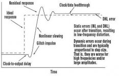
....If the error of DAC come at the step respone(overshoot or undershoot),I don't think you can easily correct it,because it is depend on the freq/time.
AD1865 said:The codes are:
0000 0000 0000 0000 0000 0000
0000 0000 0000 0000 0000 0001
0000 0000 0000 0000 0000 0010
0000 0000 0000 0000 0000 0100
...
0100 0000 0000 0000 0000 0000
and
1000 0000 0000 0000 0000 0000
1000 0000 0000 0000 0000 0001
1000 0000 0000 0000 0000 0010
1000 0000 0000 0000 0000 0100
...
1100 0000 0000 0000 0000 0000
(Because PCM1704 is two 23 bit DAC)
....If the error of DAC come at the step respone(overshoot or undershoot),I don't think you can easily correct it,because it is depend on the freq/time.
Deglitcher?
Sorry, I can't understand. My opinion is that I have no idea about correcting the dynamic error caused by setting time.Bernhard said:Isn`t the step response removed by the deglitcher if we use one ?
First to my understanding, the deglitcher removes the part of the signal where it changes on each sample and
second if we use only 4x os or even non os and a chip like 1702 can do 16 x os, then it should have been settled and stable and static.
Instead of endless discussions one should try and if it works, it is good and if not, try something else.
second if we use only 4x os or even non os and a chip like 1702 can do 16 x os, then it should have been settled and stable and static.
Instead of endless discussions one should try and if it works, it is good and if not, try something else.
- Status
- Not open for further replies.
- Home
- Source & Line
- Digital Source
- A good way to reduce R-2R DAC linear error