A good way to reduce R-2R DAC liner error
For example, we can record the output current of selected PCM1704 with the input code from 000000 to FFFFFF. Then we can use computer to correct the code with minimum liner error. Save the input code and the correct code to an EPROM and use a CPLD to convert the code, we can have much better performance.
For example, we can record the output current of selected PCM1704 with the input code from 000000 to FFFFFF. Then we can use computer to correct the code with minimum liner error. Save the input code and the correct code to an EPROM and use a CPLD to convert the code, we can have much better performance.
Re: A good way to reduce R-2R DAC liner error
I had posted that idea recently, the big big problem is that for a PCM1704 you have to measure 16 000 000 ( in words: 16 million )codes.
No idea how fast DVMs are, maybe you can get a 6 1/2 DVM with 10 measurements / s, it will take 19 days.
You need a software that compares the measured current with the theoretical current and stores the 24 bit code at the 16bit code adress of the eprom.
There have been answers how to simplify that, but nothing really helpful.
Somebody would have to write a program that reeads data from DVM, sends data to PCM1704, compares data with a table of currents, decides if the read data from the DVM is inside the window of what is acceptable deviation, writes a file that can be read by an eprommer.
😀 😀 😀 😀 😀 😀 😀
Now please nobody tell me that this can be done very simple with a DSP &%§$§* unless doing it for me.
AD1865 said:For example, we can record the output current of selected PCM1704 with the input code from 000000 to FFFFFF. Then we can use computer to correct the code with minimum liner error. Save the input code and the correct code to an EPROM and use a CPLD to convert the code, we can have much better performance.
I had posted that idea recently, the big big problem is that for a PCM1704 you have to measure 16 000 000 ( in words: 16 million )codes.
No idea how fast DVMs are, maybe you can get a 6 1/2 DVM with 10 measurements / s, it will take 19 days.
You need a software that compares the measured current with the theoretical current and stores the 24 bit code at the 16bit code adress of the eprom.
There have been answers how to simplify that, but nothing really helpful.
Somebody would have to write a program that reeads data from DVM, sends data to PCM1704, compares data with a table of currents, decides if the read data from the DVM is inside the window of what is acceptable deviation, writes a file that can be read by an eprommer.
😀 😀 😀 😀 😀 😀 😀
Now please nobody tell me that this can be done very simple with a DSP &%§$§* unless doing it for me.
Re: A good way to reduce R-2R DAC liner error
Hi
Question: Why does the error occur ?
regards
AD1865 said:For example, we can record the output current of selected PCM1704 with the input code from 000000 to FFFFFF. Then we can use computer to correct the code with minimum liner error. Save the input code and the correct code to an EPROM and use a CPLD to convert the code, we can have much better performance.
Hi
Question: Why does the error occur ?
regards
You have such a succinct manner of stating what I am thinking. Maybe we should make you a moderator, with the ability to erase some of these pointless threads.
Jocko
Jocko
Re: Re: A good way to reduce R-2R DAC liner error
Maybe because there is an error ? 😀
Or did you find any statement in the datasheet like:
The PCM1704 is the worlds first errorless DAC which is fully monotonic and guarantees 24 bit linearity in the K-selection ?
Guido Tent said:
Question: Why does the error occur ?
Maybe because there is an error ? 😀
Or did you find any statement in the datasheet like:
The PCM1704 is the worlds first errorless DAC which is fully monotonic and guarantees 24 bit linearity in the K-selection ?
Read this carefully and try to understand:
Quote from the PCM1702 datasheet:
Even though absolute integral and differential linearity specs are not given for the PCM1702, the extremely low THD+N performance is typically indicative of 17-bit integral linearity in the DAC. The relationship between THD+N and linearity, however is not such that an absolute linearity specification for every individual output code can be guaranteed.
The PCM1704 datasheet is missing some specs.
Re: A good way to reduce R-2R DAC liner error
Hi AD1865,
Better use an AD1865JK not needing adjustment.........
😎
AD1865 said:For example, we can record the output current of selected PCM1704 with the input code from 000000 to FFFFFF. Then we can use computer to correct the code with minimum liner error. Save the input code and the correct code to an EPROM and use a CPLD to convert the code, we can have much better performance.
Hi AD1865,
Better use an AD1865JK not needing adjustment.........
😎
I have never been fond of the low-level linearity in the >20-bit B-B DACs, compared to say.........the AD1862.
Still, I have better things to do other than worry about it.
More power to you if you have the time and energy to expend on such ventures.
Jocko
Still, I have better things to do other than worry about it.
More power to you if you have the time and energy to expend on such ventures.
Jocko
I guess AD1865 means there is 8-bit extra dynamic range for the PCM1704.
We might make use of the extra bits, setup a calibration file in the interpolation filter to compensate low level linearity error.
But like Jocko said, the linearity error of PCM1704 is so small that I wouldn't be bothered too.
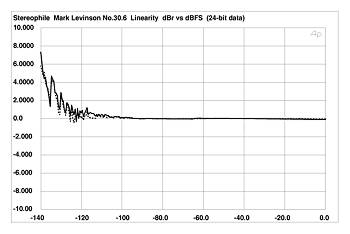
Mark No.30.6 measurement
We might make use of the extra bits, setup a calibration file in the interpolation filter to compensate low level linearity error.
But like Jocko said, the linearity error of PCM1704 is so small that I wouldn't be bothered too.
Mark No.30.6 measurement
AD1865 , Bernhard , how do you plan to correct any deviation that is less than a single bit increment or decrement in size?
I am not sure anymore if I should take your posts serious.
The deviation will be more than one bit unless the DAC has 24bit linearity.
This is a 24bit resolution DAC not 24bit linearity.
AD1865 meant to pick out 65000 codes out of 16000000 codes to get a near perfect 16 bit DAC.
Something like a triple crown TDA1541.
Same with me.
But it will be much more easy to use one DAC per bit.
No, I think it would be easier to use a PCM1704 and learn to live with its limitations.
Or '179x...........they already have a lot of number crunching going on inside of them.
Jocko
Or '179x...........they already have a lot of number crunching going on inside of them.
Jocko
Bernhard said:AD1865 meant to pick out 65000 codes out of 16000000 codes to get a near perfect 16 bit DAC. Something like a triple crown TDA1541.
Since when is TDA1541 a near perfect 16 bit DAC ??
It's worse than that,he's dead, Jim!!
You miss the point. You dont get to cherry pick values.
There is a precise output value for every input value and it is related to the full scale output value. There is also a fixed relationship between a 24bit word and a 16bit word, i.e. every single value of the 16 bit word maps to every 256th value of the 24 bit word. 0000 0000 0000 0001 will yield the same output value as 0000 0000 0000 0001 0000 0000 assuming the same full scale output value.
So I'll ask you again. How do you plan to correct any measured deviation that is less than 1 LSB or 1 quantization step?
Bernhard said:I am not sure anymore if I should take your posts serious.
The deviation will be more than one bit unless the DAC has 24bit linearity.
This is a 24bit resolution DAC not 24bit linearity.
AD1865 meant to pick out 65000 codes out of 16000000 codes to get a near perfect 16 bit DAC.
Something like a triple crown TDA1541.
Same with me.
But it will be much more easy to use one DAC per bit.
You miss the point. You dont get to cherry pick values.
There is a precise output value for every input value and it is related to the full scale output value. There is also a fixed relationship between a 24bit word and a 16bit word, i.e. every single value of the 16 bit word maps to every 256th value of the 24 bit word. 0000 0000 0000 0001 will yield the same output value as 0000 0000 0000 0001 0000 0000 assuming the same full scale output value.
So I'll ask you again. How do you plan to correct any measured deviation that is less than 1 LSB or 1 quantization step?
Not to correct it to 16bit DAC
Yes, I can't correct the measured deviation which is less than 1 LSB, but may be the selected PCM1704 can have perfect 20bit precision when I correct the code. That mains the total THD maybe -120dB THD when 0dB output. So I don't want to restrict it to perfect 16 bit DAC or 20 bit DAC..., but to reduce the THD(either low or high level output).
I will say, the PCM1704 of Mark Levinson NO30.6 DAC has been manual adjusted, if you see other DAC which also use PCM1704 you will find the difference. And I think low level THD is importance, but the high level THD is also important. In my way, it can reduce much error in high level output.
BTW, TDA1541 is a good DAC, it's integral linearity error and differential linearity error are less than 0.5 LSB.
Well, if you think that it is a good DAC, then by all means keep using it.
All this angst about low-level linearity, and yet I bet you are using the stock clock, and an op-amp for the I/V.
Jocko
All this angst about low-level linearity, and yet I bet you are using the stock clock, and an op-amp for the I/V.
Jocko
I use bjt or FET as I/V
If use digital filter, I would like use PCM1704. This can reduce the filter error.
In my way, it can eliminate the glitch when input code increase but the ouput is decrease, which I think can reduce "digital sound". Although NFB BJT I/V linearity is not as good as OP, but it can reduce RF noise, and the output no glitch like DAC.
PCM1702/4, PCM63 can only eliminate the glitch around zero but not high level output.
Re: Not to correct it to 16bit DAC
But that you cannot correct the code because you do not have access to the current sources. All you can do is map your 20 bits to the upper 20bits of the PCM1704.
AD1865 said:Yes, I can't correct the measured deviation which is less than 1 LSB, but may be the selected PCM1704 can have perfect 20bit precision when I correct the code.
But that you cannot correct the code because you do not have access to the current sources. All you can do is map your 20 bits to the upper 20bits of the PCM1704.
Re: I use bjt or FET as I/V
WRT NFB I-V linearity is not as good as OPA...
Says who?
Terry
AD1865 said:
Although NFB BJT I/V linearity is not as good as OP, but it can reduce RF noise, and the output no glitch like DAC.
WRT NFB I-V linearity is not as good as OPA...
Says who?
Terry
- Status
- Not open for further replies.
- Home
- Source & Line
- Digital Source
- A good way to reduce R-2R DAC linear error