I need a good output amplifier for a generator. Specs are pretty normal: 30Vpp output, 1MHz bandwidth, 50 ohm capability, but I also want sub-ppm linearity performance, which seriously complicates matters.
However, thanks to the topology, I only need an inverting configuration, which somewhat eases the problem: no need for a NI input, and no common-mode induced distortion.
This makes me think that I could get away with a relatively simple configuration, whereas an opamp-like topology would require two or three dozens of transistors.
I didn't find any satisfactory solution so far, neither of my own nor internet-inspired.
Does someone have a good (clever) starting base to propose?
The impedance level is relatively low, which should also simplify the problem.
This summarizes what I am looking for:
Presumably some high-order conditionally stable loop to have a decent amount of loop gain at 1 MHz and its harmonics. Can the output stage be a class-A stage with 250 or 500 mA bias current?
Yeah, 30^2/(sqrt(8) * 50) means a 7W @ 1 MHz power bandwidth, which isn't trivial! That output stage is going to be tricky. My gut would be to have some sort of IC front-end, discrete power stage-with gain on the back composite. How much gain are we talking about as well?
Is the load always 50 ohm or can it vary all over the place? Is a first-order series filter at the output allowable to stabilize the load impedance at high frequencies?
I once came up with this idea (post 3444 of the thread, see also post 3425) for a high-order amplifier, no idea if it works:
https://www.diyaudio.com/community/...audio-amplifiers.240712/page-173#post-3761088
The output stage would have to be modified to work in class A. Advantages of class A are that the output stage distorts less and that you don't get grossly distorted currents magnetically coupling to something they shouldn't couple to.
Last edited:
Non-inverting will be easier than inverting from what I'm seeing in datasheets of high speed opamps like the LT6228/6229 - those can do -120dB H2 and -130dB H3 at 1MHz for gain of +1 but not for inverting -1 or even +2. Thats into 1k though, so you'd have to parallel 20 of them, and the swing is only 2Vp-p, distortion goes up rapidly with amplitude.
A simple circuit isn't the way to go for ultra-performance like this, you need lots of gain, probably multiple nested feedback loops, very careful design and I suspect something like an Analog Devices fast opamp is going to be the best place to find such performance. All the stray capacitance in a discrete circuit will be a killer too I fear. At 1MHz 1pF is 160k, which is 2% of your feedback conductance, so the non-linearities in stray capacitance will probably limit performance (use teflon coated wires, teflon PCB?)
Not sure you asking for an achievably goal, but paralleling some LT6229's is the closest I can find to such levels of performance, and they only handle +/-5V rails... Perhaps using these as an error-corrector is possible?
Presumably some high-order conditionally stable loop to have a decent amount of loop gain at 1 MHz and its harmonics. Can the output stage be a class-A stage with 250 or 500 mA bias current?
I toyed with the idea, but "having a decent amount of loop gain" at 3, 5, 7MHz looks difficult. If I cannot avoid it, class A is an option.
How much gain are we talking about as well?
As indicated on the sketch, around 5x
Is the load always 50 ohm or can it vary all over the place? Is a first-order series filter at the output allowable to stabilize the load impedance at high frequencies?
It can be comprised between 50 and infinity, and be reactive as well
I once came up with this idea (post 3444 of the thread, see also post 3425) for a high-order amplifier, no idea if it works:
I'll give it a try anyway
Non-inverting will be easier than inverting from what I'm seeing in datasheets of high speed opamps like the LT6228/6229 - those can do -120dB H2 and -130dB H3 at 1MHz for gain of +1 but not for inverting -1 or even +2. Thats into 1k though, so you'd have to parallel 20 of them, and the swing is only 2Vp-p, distortion goes up rapidly with amplitude.
Interesting, it comes as a surprise as I have always taken for granted the lower THD for inverting configurations
Perhaps using these as an error-corrector is possible?
Yes, that is one of the options I began to explore. Combining the error-corrector harmoniously with the rest of the circuit is not simple though
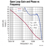
I think the LT6228/6229 works best as a voltage follower because it then has a larger loop gain than in any other configuration. With its gain-bandwidth product of 890 MHz, its loop gain is about 890 (or -890 j) at 1 MHz and 445 (or -445 j) at 2 MHz as a voltage follower and half of that when the closed-loop gain is set to -1 or +2.
Attachments
I have explored the error-correction idea.
As a model, I have used a low-performance main amplifier, to be able to see easily the imperfections and the way the correction deals with them.
The main amplifier is U1 and a discrete buffer, and its output is summed with the correcting amplifier via a resistive summer made of R5/R7.
The correction amplifier has various options: B1 is an ideal spice amplifier, and it gives good results obviously:

A real opamp (U2) is another possibility, but things degrade very quickly when used directly:

One of the problems is that the corrector's output is ~0 (ideally anyway), but it is connected to the full output voltage via R7, resulting in a large output current.
In the sim, this can be fixed by referencing the corrector to the output, but in the real world things would be much more complicated:

Another fix is to insert an ideal spice buffer between the corrector's output and R7:

All of this seems to indicate that the corrector amplifier needs to be exceptionally good, although it shouldn't in theory: it only deals with small voltages, and its output is diluted in a 1:10 ratio.
As a model, I have used a low-performance main amplifier, to be able to see easily the imperfections and the way the correction deals with them.
The main amplifier is U1 and a discrete buffer, and its output is summed with the correcting amplifier via a resistive summer made of R5/R7.
The correction amplifier has various options: B1 is an ideal spice amplifier, and it gives good results obviously:
A real opamp (U2) is another possibility, but things degrade very quickly when used directly:
One of the problems is that the corrector's output is ~0 (ideally anyway), but it is connected to the full output voltage via R7, resulting in a large output current.
In the sim, this can be fixed by referencing the corrector to the output, but in the real world things would be much more complicated:
Another fix is to insert an ideal spice buffer between the corrector's output and R7:
All of this seems to indicate that the corrector amplifier needs to be exceptionally good, although it shouldn't in theory: it only deals with small voltages, and its output is diluted in a 1:10 ratio.
Attachments
According to the schematic in post #1, you wanted a 0 ohm output, now it's 50 ohm. What do you want? If it's 50 ohm, is that 30 V peak-peak the terminated-with-50-ohm or the open-circuit output voltage?
With a simple gain block, like in post #1, the impedance has to be zero so that only the 50ohm resistor defines the external output impedance, very much like most signal generators.
The 30Vpp is open-circuit.
With a more complex arrangement like the error-correcting one, the requirement is to have a final equivalent impedance = 50ohm.
Since the output has to tolerate a short, the amplifier(s) needs to be able to drive 50ohm
The 30Vpp is open-circuit.
With a more complex arrangement like the error-correcting one, the requirement is to have a final equivalent impedance = 50ohm.
Since the output has to tolerate a short, the amplifier(s) needs to be able to drive 50ohm
You could also use a combination of series and shunt feedback to set the 50 ohm output resistance, although I don't see any advantage to doing so in this case. As the circuit has to work well with shorted and open output, the output stage still needs to support 30 V peak-peak and 600 mA peak-peak.
A synthetic output impedance might ease voltage swing constraints, but replacing a purely passive component with active ones is probably going to add non-linearities; not absolutely certain though: a very clever circuit might simulate the output impedance AND reduce the non-linearities, but for the moment I do not feel clever enough to implement such a wonder.
I need to sleep over it, once, twice, or more, maybe the illumination will come...
For the moment, what I find disturbing is the required quality level of a possible error-correcting amplifier: back-of-an-envelope calculations seemed to suggest that it should be relatively unimportant, but even a sim already shows that it is not the case
It doesn't ease voltage swing constraints when the generator has to work with output open and it doesn't ease current swing constraints when the generator has to work with output shorted...
Why do you simulate at 10 kHz instead of 1 MHz?
Why do you simulate at 10 kHz instead of 1 MHz?
I have used a crappy TLO82 as a main amplifier, to be able to observe realistic flaws and the effect the corrector has on them, but operating the same amplifier at 1MHz is science-fiction.
Other truly 1MHz-capable amplifiers, (native in the LTspice library), give such impossibly good results in the sim that they are not usable to test a correcting scheme: they already pass with flying colors by themselves, but I know for sure that the reality is quite different.
Therefore, I use a "small steps" approach: when I find a good, effective and tolerant scheme working at low frequencies, I can adapt it to higher frequencies
I am currently exploring another promising circuit, courtesy of Suzyj:
https://www.diyaudio.com/community/threads/does-anyone-recognise-this-topology.302358/post-4954495
It is already quite good in its original form, but I need to improve it significantly.
With 24V supplies, it manages 0.2% THD @1MHz:

One of the causes of distortion is an imperfect crossover: the output transistor that was conducting doesn't turn off instantly, and this conduction tail influences the output because of the 10 ohm resistors.
By shunting them with fast diodes, the newly active transistor immediately takes control and eliminates the artefacts.
The result is a reduction to 1/3rd of the THD:

Another issue is the loading of the feedback divider by Q5/6.
Reducing the resistors values is not a realistic option, but by including a CFP-inspired buffering layer, the THD can be reduced by a further factor of 3:

A similar approach is to insert a fixed current gain in the collectors of Q5/6:

The THD has now dropped below 10ppm.
Ideally, I would like to drop the non-inverting input, which would be possible in a 50 ohm environment, but much more difficult at 560 ohm, unfortunately: it would have simplified the circuit, and reduced the non-linearity even further.
Does anyone see other low-hanging fruits to be picked somewhere in this circuit?
https://www.diyaudio.com/community/threads/does-anyone-recognise-this-topology.302358/post-4954495
It is already quite good in its original form, but I need to improve it significantly.
With 24V supplies, it manages 0.2% THD @1MHz:
One of the causes of distortion is an imperfect crossover: the output transistor that was conducting doesn't turn off instantly, and this conduction tail influences the output because of the 10 ohm resistors.
By shunting them with fast diodes, the newly active transistor immediately takes control and eliminates the artefacts.
The result is a reduction to 1/3rd of the THD:
Another issue is the loading of the feedback divider by Q5/6.
Reducing the resistors values is not a realistic option, but by including a CFP-inspired buffering layer, the THD can be reduced by a further factor of 3:
A similar approach is to insert a fixed current gain in the collectors of Q5/6:
The THD has now dropped below 10ppm.
Ideally, I would like to drop the non-inverting input, which would be possible in a 50 ohm environment, but much more difficult at 560 ohm, unfortunately: it would have simplified the circuit, and reduced the non-linearity even further.
Does anyone see other low-hanging fruits to be picked somewhere in this circuit?
Attachments
- Home
- Amplifiers
- Solid State
- A good TIA/inverting gain block idea?