Hi! I'm new here and I'm about to build a pair of bridged LM4780-amps. I've searched a hole lot but I haven't found a good single sided PCB for a bridged LM4780. Does anyone have one that I can use right of?
😀mightydub said:DIY!

But don't even try. It is next to impossible. Due to the pin layout you have to pass power traces in between pins that are much too narrowly spaced for the required trace width. People, who know how to make a single-sided version for the LM4780 also know that it makes no sense.
If you want a two-channel IC that can be implemented on a single-sided PCB, use the LM1876 (2 x 20 W), the LM4765 (2 x 30 W) or the LM4766 (2 x 40 W) without connecting the mute and stand-by functions. Else use a double-sided PCB or two LM3886.
impossible is nothing my friend...
impossible is nothing my friend...check this out , i have made a dozens of this at home..
http://diygainclone.blogspot.com/2008/07/evolution-of-pcbs-for-lm4780-based.html
pacificblue said:
😀
But don't even try. It is next to impossible. Due to the pin layout you have to pass power traces in between pins that are much too narrowly spaced for the required trace width. People, who know how to make a single-sided version for the LM4780 also know that it makes no sense.
impossible is nothing my friend...check this out , i have made a dozens of this at home..
http://diygainclone.blogspot.com/2008/07/evolution-of-pcbs-for-lm4780-based.html
Re: impossible is nothing my friend...
On the other hand using jumpers is cheating, is it not? 😉
I know. That's why I only wrote "next to impossible".kuldeepsingh said:impossible is nothing my friend...[/url]
On the other hand using jumpers is cheating, is it not? 😉
Re: Re: impossible is nothing my friend...
no dear, cheating to whom?.. the purpose should me solved. it was difficult to get double sided blank PCB at my place and even if i get one, it is more difficult to match top and bottom layer for correct hole drilling,
but here using jupers, i achieved very good results, but there are no jumpers in the signal path, i had only 4 jumpers in my final layout, which i feel is quite a decent number keeping simplicity of layout in mind.
pacificblue said:
On the other hand using jumpers is cheating, is it not? 😉
no dear, cheating to whom?.. the purpose should me solved. it was difficult to get double sided blank PCB at my place and even if i get one, it is more difficult to match top and bottom layer for correct hole drilling,
but here using jupers, i achieved very good results, but there are no jumpers in the signal path, i had only 4 jumpers in my final layout, which i feel is quite a decent number keeping simplicity of layout in mind.
Re: Re: impossible is nothing my friend...
This means that also using dual layer PCB is cheating, as it serves the same purpose: the shortest routes as possible. Isn't it? 😀
pacificblue said:
On the other hand using jumpers is cheating, is it not? 😉
This means that also using dual layer PCB is cheating, as it serves the same purpose: the shortest routes as possible. Isn't it? 😀
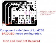
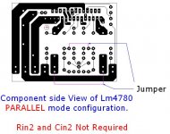
bridged and paralleled
Mmm, theoritically the same PCB can be used, but i had never tried. it may look like this, but you please check it thoroughly.
Ulew said:Is it bridged?
Mmm, theoritically the same PCB can be used, but i had never tried. it may look like this, but you please check it thoroughly.
Attachments
Cobra2 said:
The bridged boards are temporarily out of stock, I sold many hundreds of them. If there's more interest I can have another batch made up.
jack
Re: Re: Re: impossible is nothing my friend...
Please don't take offense. I've seen pictures of your amplifier and I am quite impressed with your work. Especially because I know after a few visits to India that the circumstances are much less favorable for such a hobby than they are e. g. here in Europe. This PCB is another example of how resourceful and ingenious you work around any obstacles you encounter.
Cheating in the sense that the jumpers make it effectively double-sided.kuldeepsingh said:no dear, cheating to whom?.. the purpose should me solved. it was difficult to get double sided blank PCB at my place and even if i get one, it is more difficult to match top and bottom layer for correct hole drilling,
but here using jupers, i achieved very good results, but there are no jumpers in the signal path, i had only 4 jumpers in my final layout, which i feel is quite a decent number keeping simplicity of layout in mind.
Please don't take offense. I've seen pictures of your amplifier and I am quite impressed with your work. Especially because I know after a few visits to India that the circumstances are much less favorable for such a hobby than they are e. g. here in Europe. This PCB is another example of how resourceful and ingenious you work around any obstacles you encounter.
I started with the remark that it was next to impossible to make a single-sided PCB for the LM4780. kuldeepsingh said he had one. Your remark shows me that you also think that jumpers make it quasi double-sided.ratza said:This means that also using dual layer PCB is cheating, as it serves the same purpose: the shortest routes as possible. Isn't it? 😀
Re: Re: Re: Re: impossible is nothing my friend...
Exactly.
pacificblue said:Your remark shows me that you also think that jumpers make it quasi double-sided.
Exactly.
Re: and paralleled
Thank you very much!
What's best, bridged or paralleled?
kuldeepsingh said:same PCb paralleled
Thank you very much!
What's best, bridged or paralleled?
Depends on your speaker impedance. Bridged for greater than or equal to 8 Ohm, parallel for smaller than or equal to 4 Ohm. Single operation for 4..8 Ohm. National's AN-1192 is a must-read on that topic.
Okay! The speakers are 8 ohm so bridged it is!
I'm kind of a noob at diy-amplifiers so can anyone tell me if the bridged version posted by kuldeepsingh is correct?
I'm kind of a noob at diy-amplifiers so can anyone tell me if the bridged version posted by kuldeepsingh is correct?
If you don't have the knowledge to find that out by yourself, you should consider reading and learning a bit first. Then start by building a standard application. You may find that you don't need more output power than that can deliver.
If you find afterwards that you do need more power (=more SPL), you can still bridge later on. But remember that you get four times as much output power in bridged mode ->
Must read and understand:
If you find afterwards that you do need more power (=more SPL), you can still bridge later on. But remember that you get four times as much output power in bridged mode ->
- - you need four times as big a power supply.
- you need four times as much heatsinking.
- you might run into heatsinking limits, especially with the LM4780 (AN-1192 again!).
- find out, if your speakers can mechanically cope with that amount of power or if you only raise distortion and risk destruction.
Must read and understand:
- - datasheet for LM4780 or any other IC you want to use.
- AN-1192 on bridging and thermal considerations.
- Linkwitz homepage on SPL, excursion limits, power requirements.
- etc.
very good advice, including all I edited out.pacificblue said:If you don't have the knowledge to find that out by yourself, you should consider reading and learning a bit first. Then start by building a standard application. ........................................... IC you want to use.
- AN-1192 on bridging and thermal considerations.
- Linkwitz homepage on SPL, excursion limits, power requirements.
- etc.[/list]
- Status
- Not open for further replies.
- Home
- Amplifiers
- Chip Amps
- A good single sided PCB for bridged LM4780?