When the heaters are cold, their resistance is lower than when heated up, so the current through the heater is higher than when heated up. This makes the heaters glow bright at start-up. Nothing to worry about; the heaters were made to withstand this.While assembling the preamp I noticed a strange fact that I had only noticed in old tube radios, namely a sudden bright glow of the tubes on powerup. Does anyone know how to explain the phenomenon, and if it is harmful? I assumed it was the regulator that for 1-2s supplies an overcurrent with the heaters not yet turned on...
Have a very close look at the related tubes. Use a magnifying lens, if possible. I bet you'll find bare, uncoated tungsten heater wire right between the welding points and the cathode tube. That's the location where this bright light is emitted from.
Best regards!
Best regards!
Yes, it is as you say ... in particular between the two points of junction between the pins and the tungsten filament (on the sides of a small glass rod) I observed the generation of that glow
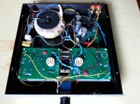
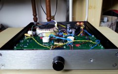
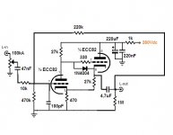
Here is the preamp made according to the suggestions in # 36. I built it as seen in a compact case and I had to study the individual spaces to house the various components (useful internal height 4 cm, hence the use of a 50VA toroidal transformer).
Attachments
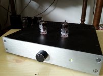
The assembled unit looks quite nice. Perhaps you'd want to put some sort of cage over the exposed tubes... ?
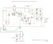
Can you post a schematic of the built circuit?
And of course, have you listened to it? How does it sound to you?
Do you have any way of measuring frequency response, noise, distortion, etc.?
Can you post a schematic of the built circuit?
And of course, have you listened to it? How does it sound to you?
Do you have any way of measuring frequency response, noise, distortion, etc.?
Thanks!
Yes, I tried it with both a solid state amp and a tube amp. The resulting sound is round but natural (not colored), it seems to me that a good combination is with the potentiometer at least half and a V (in) <1V (as it amplifies 3-4 times).
I haven't done distortion measurements yet, maybe I'll try REW and basic measurements with the Hantek.
In the meantime, I will soon insert the schematics.

Well, I'm not sure the feedback loop was implemented correctly.
When I simulate your circuit, and I break the feedback loop by removing the 220k resistor going from the output to the grid of the input tube, the circuit provides 11.6X gain (21dB of gain open loop).
When I re-connect that 220k resistor to restore the NFB loop, your circuit now provides 7.3X gain (17dB). That's only 4dB of gain reduction, and even that's not all coming from NFB.
The 470k resistor from the input tube grid to ground is unnecessary. It's just shunting signal to ground by forming a voltage divider with the 10k series resistor. I think you should get rid of that 470k resistor. The input tube grid has a path to ground through the 220k feedback resistor to the 1M output load resistor. You could reduce the value of the 1M resistor to 470k with no problem. Maybe even 220k, if you're worried about the loading of the input tube grid.
If you want about 3.5X gain (10dB, or 11dB of NFB), try changing the 10k series resistor to 47k, which will define a ratio of approximately 4.7:1 for the 220k/47k feedback voltage divider.
Why do you need the 100pF capacitor from input tube grid to ground? Are you worried about HF oscillations?
Also, I think the input DC blocking cap (47nF) is too small in value. That cap and the series NFB resistor define a low frequency pole. The way you have it, the cutoff frequency (low frequency -3dB down point) will be around 125Hz, if my simulation is correct.
If you change that value, you will need to increase the value of the input blocking capacitor. Remember, F3 = 1/2piRC, so a 10k series NFB resistor will need a blocking cap of about 2.2uF at least.
I hope that helps.
When I simulate your circuit, and I break the feedback loop by removing the 220k resistor going from the output to the grid of the input tube, the circuit provides 11.6X gain (21dB of gain open loop).
When I re-connect that 220k resistor to restore the NFB loop, your circuit now provides 7.3X gain (17dB). That's only 4dB of gain reduction, and even that's not all coming from NFB.
The 470k resistor from the input tube grid to ground is unnecessary. It's just shunting signal to ground by forming a voltage divider with the 10k series resistor. I think you should get rid of that 470k resistor. The input tube grid has a path to ground through the 220k feedback resistor to the 1M output load resistor. You could reduce the value of the 1M resistor to 470k with no problem. Maybe even 220k, if you're worried about the loading of the input tube grid.
If you want about 3.5X gain (10dB, or 11dB of NFB), try changing the 10k series resistor to 47k, which will define a ratio of approximately 4.7:1 for the 220k/47k feedback voltage divider.
Why do you need the 100pF capacitor from input tube grid to ground? Are you worried about HF oscillations?
Also, I think the input DC blocking cap (47nF) is too small in value. That cap and the series NFB resistor define a low frequency pole. The way you have it, the cutoff frequency (low frequency -3dB down point) will be around 125Hz, if my simulation is correct.
- For testing purposes, maybe you should short out that 47nF input blocking cap for now, while you decide on the value of the series NFB resistor that gets you the gain you want.
- After you know what the value of the series NFB resistor will be, then figure out the value of the input blocking cap for your desired F3.
( F3 = 1/2piRC )
- After you know what the value of the series NFB resistor will be, then figure out the value of the input blocking cap for your desired F3.
- For about 3.5X gain, increase the value of the series FB resistor from 10k to 47k (or 51k).
- Remove the 470k resistor from the input tube grid to ground.
- Remove the 100pF capacitor from the input tube grid to ground.
If you change that value, you will need to increase the value of the input blocking capacitor. Remember, F3 = 1/2piRC, so a 10k series NFB resistor will need a blocking cap of about 2.2uF at least.
I hope that helps.
Last edited:
What does your simulation say about gain if the 470k is removed? Does it change at all?
Best regards!
Best regards!
Yes, removing the 470k grid leak resistor increases the gain just a smidge. With 100mV input, from 742mV output with that 470k removed down to 732mV out with it installed. Just 10mV of difference. OK, I was picking nits with that one.
That slight reduction in gain is because the 470k resistor is located in the circuit inside the feedback loop. If you move it to the other side of the 10k (series NFB) resistor, then it will be outside (before) the feedback loop, in parallel with the volume control (connected from wiper to ground). Or remove it altogether because it's not needed.
Being that the 12AU7 does make more distortion than other types, I'd use more NFB. With the circuit the way it is now, the simulation predicts 0.08% THD with 1V rms output (using Adrian Immler's i5 model of 12AU7). Increasing the value of the series NFB resistor to 47k and increasing the value of the series blocking cap to 1uF reduces gain to 3.2X and THD to 0.04%.
Last edited:
That's exactly what I've expected. The input triode grid is almost grounded virtually. Hence, I'd also not increase the input resistor, 'cause it adds noise, but decrease the NFB resistor instead to reduce gain and THD.
Best regards!
Best regards!
Actually, first I had run the simulation with the potentiometer at half scale, so I had miscalculated.
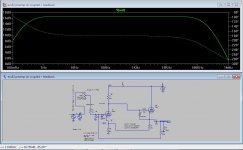
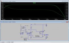
From my own simulations I can confirm your statements: the first graph is with R2 = 10k and V (in) / V (out) = 7: 1 (+ 17dB) while the second with R2 = 27k has a ratio of 4: 1 (+ 12dB). This last value I think will fit.
The small C (in) of 100pF is not for fear of oscillation but it seemed to improve the simulation noise but it's useless indeed (so removable).
From what I have seen, in my opinion, lowering the gain too much leads to a slight increase in THD, due to the role of feedback too. So at this point a 12dB gain should be OK for me...
Attachments
Increasing the value of the input (series) resistor adds noise, but this circuit runs at line level. so I don't think that would be much of an issue using quality metal film resistors.That's exactly what I've expected. The input triode grid is almost grounded virtually. Hence, I'd also not increase the input resistor, 'cause it adds noise, but decrease the NFB resistor instead to reduce gain and THD.
Best regards!
In a single-stage anode follower (inverter), making the parallel NFB resistor too small a value puts a heavier load on the triode, bringing with it the possibility of increased distortion from overly loading down the triode. But this circuit has that cathode follower buffer before the NFB loop. Does that make it relatively immune from being overly loaded down, and therefore you can go ahead and use a NFB loop of Rseries = 10k and Rparallel = 47k, without loading down V1?
From what I have seen, in my opinion, lowering the gain too much leads to a slight increase in THD, due to the role of feedback too.
Loweing the gain by increasing NFB will decrease THD, not increase it. Did you measure this to verify it?
If you go crazy with NFB you can run into instability, ringing, oscillation. However, I don't think 15dB of NFB is going to make this circuit unstable. Again, the only pole in the whole circuit is that output blocking capacitor. Make that large enough in value and I don't see how you can make a phase shift happen that would cause ringing and/or oscillation.
Simulation predicted that the circuit as shown will make 0.08% THD at 1V rms output. That's kind of high THD for a hi-fi line stage. It confirms the idea that the 12AU7 makes too much distortion for use in hi-fi, don't you think?
I'd apply more NFB in this situation. But that's just me...
I was actually referring to what I saw from the simulation. I know it goes against the trend of normal NFB behavior, but I have noticed this by dropping too much in value. I don't know...
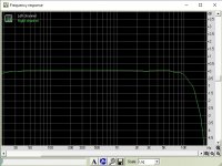
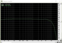
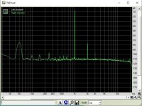
Anyway, I did a first analysis on the frequency response and the THD with the RMAA software (I still have to improve it because it has been newly installed). The first graph relates to the external sound card, the second to the preamp. The third shows a THD of about 0.03% measured at half turn of the potentiometer, that is ~0.6Vrms out, from an input signal from the soundcard of 0.15-0.2V. For an analysis of higher values I'd better use a resistive divider with this software.
Attachments
Last edited:
Hey, the THD looks better than expected, but the 50Hz hum is showing a bit high.
What sound card are you using with the software?
What sound card are you using with the software?
Yes, in effect it is fine result...maybe I'll permform other tests and verify the goodness of this.
I have just a doubt, the frequency response doesn't seem a bit lacking on the high side? I noticed -3dB rolloff at 17khz starting from 5 khz...
I have just a doubt, the frequency response doesn't seem a bit lacking on the high side? I noticed -3dB rolloff at 17khz starting from 5 khz...
Yes the input capacitor (47nF) was already removed before testing.
Rongon, the soundcard is a cheap Behringer UCA202.
Rongon, the soundcard is a cheap Behringer UCA202.
Regarding the HF roll-off (-3dB @ 17kHz)
In the screenshots from the RMAA software, you mentioned that the first 'related to the external sound card' and the second to the preamp.
If the frequency response above 10kHz is attenuated by the sound card, then it may be that the preamp is not attenuating those higher frequencies. What did you mean when you wrote that the first screenshot was related to the external sound card?
Last edited:
I meant the capacitor C2 from grid to ground. And even the simulation results in #72 indicate the input resistor's influence on HF rolloff.
Best regards!
Best regards!
- Home
- Amplifiers
- Tubes / Valves
- A good route to a ECC82 preamp