Hello,
based on an overview from an old forum thread, that is:
https://www.diyaudio.com/community/threads/tube-buffer-preamp-design.326689/
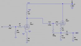
I was wondering if a schematic from the first picture I attached here would be a good choice for a low gain line preamp (or to call it "pseudo-buffer").
This arises from the need that a large gain is not needed and something like 6dB may be sufficient. Of course, since the two stages together amplify by 12 times globally, it is necessary, for example, a resistive divider at the input that attenuates the signal.
I took this simple circuit from audioxpress as a reference for the thing, adapting it to my tubes and operating characteristics.
https://audioxpress.com/article/you-can-diy-repurposing-an-old-preamp-for-line-level-duty
If there is any opinion about it ... thank you
based on an overview from an old forum thread, that is:
https://www.diyaudio.com/community/threads/tube-buffer-preamp-design.326689/
I was wondering if a schematic from the first picture I attached here would be a good choice for a low gain line preamp (or to call it "pseudo-buffer").
This arises from the need that a large gain is not needed and something like 6dB may be sufficient. Of course, since the two stages together amplify by 12 times globally, it is necessary, for example, a resistive divider at the input that attenuates the signal.
I took this simple circuit from audioxpress as a reference for the thing, adapting it to my tubes and operating characteristics.
https://audioxpress.com/article/you-can-diy-repurposing-an-old-preamp-for-line-level-duty
If there is any opinion about it ... thank you
Attachments
I'm still using an old Bottlehead Foreplay, which is basically the same as your first schem., just without C14, and there are no grid stoppers. It also has a CCS on the plate of the VA.
jeff
jeff
You have designed an inverting amplifier. Now, if the preceding stage or source is a low impedance one, I'd prefer NFB from the output to the input grid instead of a voltage divider. It would mean less noise and less THD.
Best regards!
Best regards!
You have designed an inverting amplifier. Now, if the preceding stage or source is a low impedance one, I'd prefer NFB from the output to the input grid instead of a voltage divider. It would mean less noise and less THD.
Best regards!
In effect, I was wondering if my draft were a proper way for attenuating the gain...instead, you suggested me that NFB it's better (even though I'd prefer to use it moderately). I got it..
In practice you dc coupled the first stage,..I'm still using an old Bottlehead Foreplay, which is basically the same as your first schem., just without C14, and there are no grid stoppers. It also has a CCS on the plate of the VA.
jeff
Just for comparison with mine, would you like to share the schematic? There's not much to do during a boring quarantine.. 
The 12au7 is much maligned.
I found it more stable than the 12ax7 and have used it in numerous projects.
I found it more stable than the 12ax7 and have used it in numerous projects.
Of course, it creates lots of distortion. Use a 6SN7 or 6CG7 instead.The 12au7 is much maligned.
The 12AX7 has 5 times as much gain. Not really designed to be sued without NFB.I found it more stable than the 12ax7 and have used it in numerous projects.
Cheers
Ian
Of course there are more linear tubes than ecc82 for a good sounding preamp...but since my demands are not high, and I have some 12AU7's to play with "tube rolling", I thought it can worth a try.
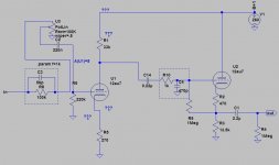
I'm also evaluating the use of an anode follower as buffer (so with no pot at input), and simulations seem to be quite good.
I'm also evaluating the use of an anode follower as buffer (so with no pot at input), and simulations seem to be quite good.

Pardon my ignorance but by what force of nature does a 12AU7 "create distortion" I've used them and they dont "create distortion" any more so than any other vacuum tube in my admittedly minimal experience.
So in order to put this silly rumor to rest why don't you link us all to done raw data that shows the 12AU7 to be a "distortion creator".
Explain it to us who have had great success building great sounding low distortion amplifier using 12AU7 tubes.
Naturally we're "all ears"
So in order to put this silly rumor to rest why don't you link us all to done raw data that shows the 12AU7 to be a "distortion creator".
Explain it to us who have had great success building great sounding low distortion amplifier using 12AU7 tubes.
Naturally we're "all ears"
Yup, that's where I first read that the "12AU7 is non-linear".
In his book "Valve Amplifiers" Third Edition, chapter 3, pp. 182-189, Morgan Jones tested a bunch of medium mu triodes in a mu-follower configuration with a triode-wired D3a as the plate load, Vg of about -3.5V from two red LEDs in series, and the plate load adjusted for 8mA plate current. He tested 28 ECC82/12AU7 tubes and found them to yield significantly higher distortion at that operating point than 6SN7 and equivalents, 5687, ECC182/7119, 6350, 7AF7, and a few others. He describes the results for the 12AU7 and 7AF7 as being "particularly ghastly."
Curiously, Merlin Blencowe also tested some 12AU7 tubes in his book "Designing High Fidelity Tube Preamps" (pp. 230-243) both with a CCS load (DN2535 cascode pair) and resistor plate load. He found the 12AU7 to be an average performer, with distortion levels on par with 6DJ8, etc.
I have no idea which are the more accurate findings.
Let’s compare Dtot of the ECC82 with Dtot of the ECC83 at:
Vb = 400 V
Ra = 100K
(see attachments)
ECC83:
Vo = 38 Veff
Dtot = 1.7 %
Vo/Vi = 63
ECC82:
Vo = 57 Veff
Dtot = 6.2 %
Vo/Vi = 14
Dtot is about proportional to Vo (see note 2 in the datasheets).
So if you ‘translate’ Dtot of the ECC82 at Vo = 57 V to Dtot of the ECC83 at Vo = 38 V you get 38/57 x 6.2 % = 4.1 %.
So at Vo = 38 V:
Dtot ECC82 = 4.1 %
Dtot ECC83 = 1.7 %
Note that this comparison doesn’t even take into account that under these circumstances the gain of the ECC82 is 14, while that of the ECC83 is 63.
Attachments
Last edited:
Thanks. I see that now.
I was looking for similar charts for ECC81 and couldn't find them in the Philips datasheets. Likewise for ECC88.
One thing that's true is that ECC83 is among the most linear triodes ever made as long as it's loaded lightly enough (as in a 330k ohm grid resistor in the following stage).
For ECC33 (similar to 6SN7) I see for Vout = 43V, Vbb = 250V, Rp = 100k, Rload = 330k that distortion = 5.4%.
https://frank.pocnet.net/sheets/129/e/ECC33.pdf
That's also many times worse than ECC83, unless I'm reading that chart wrong. Yet the ECC33 and 6SN7 enjoy a reputation for being the most linear of the twin triodes.
Since I can't find the same charts showing operating points and expected distortion for other triodes like ECC88, ECC81, 5687, ECC182, etc. then I guess we only have a very few data points to go by.
The other thing is that ECC83 is a high-mu triode (mu = 100) while ECC82 is medium-mu (mu = 20). In the proposed circuit, if you put an ECC83 for V1 the resulting amplifier will have far too much gain to be used as a line stage. So now you'll want to use some negative feedback to bring the gain back down (and there's nothing wrong with that!).
Last edited:
ECC33 is not similar to 6SN7 , but in General Electric datasheet 6SN7 has 5% distortion at 51Vrms max output , gain is 15 and 240K load , which is very close to ECC82 ...
ECC83 is for low current , a driver working close to 10mA plate current will distort more
Anyway there is nothing wrong with ECC82 , I consider it sounds very good .
ECC83 is for low current , a driver working close to 10mA plate current will distort more
Anyway there is nothing wrong with ECC82 , I consider it sounds very good .
Hi Ian, i just opened your tests of 6CG7 and 6SN7 wired as mu followers and you posted here. They were quite extensive with tubes wired as mu followers, they point to larger anodes of 6SN7 and 6CG7 having lower distortion than with smaller anodes.Just read the extensive tests made by Morgan Jones.
Cheers
Ian
Iiirc you mentioned ECC82 has 4x as much distortion as 6SN7 because of smaller anode, i'm not sure if you measured it or got this information from Morgan Jones. Can you please tell more about ECC82 distortion, i know it is not commonly used in pro audio but i see it very often in audiophile diy.
Miha
Last edited:
Same kind of comparison as in post #14, but now between the ECC82 and the ECC40:
Vb = 400 V
Ra = 100 K
Grid resistor next stage = 330K
(see attachments)
ECC82:
Vo = 57 Veff
Dtot = 6.2 %
Vo/Vi = 14
Ia = 2.6 mA
ECC40:
Vo = 76 Veff
Dtot = 3.9 %
Vo/Vi = 24
Ia = 2.2 mA
Dtot is about proportional to Vo.
So if you ‘translate’ Dtot of the ECC40 at Vo = 76 Veff to Dtot of the ECC82 at Vo = 57 Veff you get 57/76 x 3.9 % = 2.9 %.
So at Vo = 57 Veff:
Dtot ECC82 = 6.2 %
Dtot ECC40 = 2.9 %
Note that this comparison doesn’t even take into account that under these circumstances the gain of the ECC82 is 14, while that of the ECC40 is 24.
Attachments
- Home
- Amplifiers
- Tubes / Valves
- A good route to a ECC82 preamp