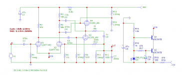
Could you maybe redraw the circuit for a slightly higher gain (ideal 3-4x) and the Vb + max 265V?
However, if the simulated features relate to the real world it would be good. Thanks.
I bring you also the schematic found on Broskie, here there is a very little difference between the two R of bootstrap, and it was after argumentated how to choose the right values:
Wow, good find. That's the circuit!
You might want to read Broskie about 'Anode Follower':
https://www.tubecad.com/2016/01/blog0336.htm
In the schematic in post #235, R1 and R2 set the amount of NFB.
Broskie seems to think that the circuit (as in post #235) is an SRPP in its essence, but with extra stuff to bring the gain up (C2 coupling the output from U2 to the plate circuit of U1).
Being that it's an SRPP in disguise, Broskie believes the circuit works in push-pull. Ah-ha! Perhaps that's why matching the plate currents of U1 and U2 results in better PSRR?
Also, Broskie mentions that the boostrap coupling cap (C2) increases PSRR, but he does not say why.
At any rate, it looks like there are good reasons why that circuit performs well, in simulation at least.
I'm behind on projects (I'm putting together a phono preamp these days) but I did have a pcb made up of a MOSFET buffered anode follower to play with. I should be able to modify the board to split the plate load resistor into two resistors and tack on a large enough value bootstrap coupling capacitor.
I wish I knew how to do a more detailed analysis of the circuit. I basically patched different ideas together that I'd read about in books and then simulated it. Without LTspice I'd be completely adrift...
Here is an older article on the anode follower and how it works:
https://www.aikenamps.com/images/Documents/anode.pdf
Incidentally, the feedback mechanism of the anode follower is exactly the same as used for an inverting op-amp. Of course the op-amp's impedances are far lower than a tube's, and the op-amp's open loop gain is far higher, but the concept is exactly the same.
https://www.electronics-tutorials.ws/opamp/opamp_2.html
https://en.wikipedia.org/wiki/Operational_amplifier_applications#Inverting_amplifier
https://www.allaboutcircuits.com/video-tutorials/the-basic-op-amp-inverting-amplifier/
https://www.electronics-tutorials.ws/opamp/opamp_2.html
https://en.wikipedia.org/wiki/Operational_amplifier_applications#Inverting_amplifier
https://www.allaboutcircuits.com/video-tutorials/the-basic-op-amp-inverting-amplifier/
Could you maybe redraw the circuit for a slightly higher gain (ideal 3-4x) and the Vb + max 265V?
In the circuit of post #265, the ratio of R2/R1 sets the gain of the anode follower. Just like in an op-amp inverting amplifier.
If the triode's open loop gain was infinite, the ratio of R2/R1 would set the gain exactly. However, the gain of a 12AU7 is much, much lower than infinity. It's more like about 16X.
The math is too complex for me to explain it, but we have LTspice to do the math anyway. 😏
I figure that with the low open loop gain of a 12AU7, making R2 about 4X the value of R1 will yield a total gain of about 3X from the completed amplifier.
In my circuit, R1 = 68k ohms. 4X that is 272k, so try a 270k ohm resistor for R2 to get a final gain of about 3X.
Try 300k for a bit more gain, 240k for a bit less. You could think of making R2 a potentiometer to adjust gain of the circuit. Like so:
The post #265 circuit will probably work as is with a 265V B+. You may need to change the value of R3 (Rk for U1) to get the plate current of U1 to match that of U2. Performance will be slightly worse with a B+ of 265V, but it should not make an audible difference.

Yes. In practice, from what I understand, he wanted to "deconstruct" the circuit and put it in parallel with the SRPP but in his own way and without going into much explanations.
Unfortunately, in the Merlin's and some others do not offer so much about it (e.g. the discussion of the anode follower is missing in the Merlin's preamp book).
So, it can be said that they are little traveled paths ... also because in my opinion most of the circuits (I'm talking about the standard ones in circulation) are based on the most classic topologies. It's the usual problem that tube "theorists" are old if not dead, so having an active interaction on certain topics isn't easy. I don't know if I've made myself clear.
Apart from that, you see that we are "in the same boat", so we say in italian.
I come from the world of chemistry (degree) but with an interest in electronics for years, so it is not easy to go into certain treatments without adequate knowledge. So I help myself also with the simulations ...
Your project sounds like an interesting thing. When it is finished if you want to share it in the forum it will certainly be appreciated ...
In #235 the AC through R4 and R8 is now different from a non bootsrapped stage - in the CCDA the DC and more particularly, the AC are the same imho. I know he talks about DC; I added my own thoughts.I'm not sure I understand.
By "have a different AC", can you tell me, AC what, exactly?
Gain? That can't be the case, because a cathode follower has about 0.95X gain due to nearly 100% NFB, while the common cathode stage has gain somewhere near the mu of the triode. Of course the gain of the first triode is also reduced by NFB, so that complicates things.
AC voltage signal swing? U2 is a cathode follower, so it should follow the voltage swing from the plate of U1.
I went back and read Broskie's CCDA article.
https://www.tubecad.com/2009/03/blog0161.htm
I don't see anything about AC current swings, just that the DC current draw from the first and second stages need to match.
I may have missed some things, though...
The U1 anode and U2 cathode have same voltage (well, almost, 95% the same..) and same DC current for sure.
To test:
- Make the internal resistance of Vb 1k (is easy) and put a probe on VB and then it should be silent in the real CCDA. It will not be with the bootstrap.
Thanks, I'll try that. It's not a problem to simply add 1k in series right after the B+ voltage source, as a test.
I also found another write-up/explanation of the proposed Bootstrapped Pair w/ NFB amplifier (circuit from post #265). The following is from the Elliott Sound Products website (Rod Elliott).
https://sound-au.com/valves/preamps.html
Scroll down to section 8, "As Good As They Come".
![preamps-f5[1].gif](https://www.diyaudio.com/community/attachments/preamps-f5-1-gif.1057852/ "preamps-f5[1].gif")
As Mr. Elliott says, "The weak point is actually the cathode follower, since its limited current and gain reduces the performance slightly." Change V2 to a high voltage MOSFET (DN2540, IRF820, STP2N60 or similar) and that situation would be improved.
In the circuit above, the NFB is brought from the output through the 240k resistor to the grid of V1. The 33k resistor in series from the input to the grid of V1 is the series load resistor for the NFB (240k) resistor. That's the voltage divider that defines the amount of output signal applied as negative feedback to the V1 grid. The ration of R2/R1 is 240k/33k = 7.27, but Mr. Elliott mentions that the gain of the completed amplifier was about 4X.
The above article was published in December 2009, which goes to show you how unoriginal I am.
Cool beans, eh?
I also found another write-up/explanation of the proposed Bootstrapped Pair w/ NFB amplifier (circuit from post #265). The following is from the Elliott Sound Products website (Rod Elliott).
https://sound-au.com/valves/preamps.html
Scroll down to section 8, "As Good As They Come".
As Mr. Elliott says, "The weak point is actually the cathode follower, since its limited current and gain reduces the performance slightly." Change V2 to a high voltage MOSFET (DN2540, IRF820, STP2N60 or similar) and that situation would be improved.
In the circuit above, the NFB is brought from the output through the 240k resistor to the grid of V1. The 33k resistor in series from the input to the grid of V1 is the series load resistor for the NFB (240k) resistor. That's the voltage divider that defines the amount of output signal applied as negative feedback to the V1 grid. The ration of R2/R1 is 240k/33k = 7.27, but Mr. Elliott mentions that the gain of the completed amplifier was about 4X.
The above article was published in December 2009, which goes to show you how unoriginal I am.
Cool beans, eh?
Do you mean the final gain of the circuit vs. the calculated gain from the feedback ratio? If so, that is expected. You only get gain equal to R2/R1 if the open loop gain is infinite. Using a wheezy 12AU7 with only 15x gain (or so), you'll get a lot less gain than R2/R1. That is to be expected from triodes.
I think a 12AT7 would be a better choice for this circuit than a 12AU7, but you know... the name of this thread is ???
I think a 12AT7 would be a better choice for this circuit than a 12AU7, but you know... the name of this thread is ???
You may find it in the MIT RADAR series, published right after WWII.2009, which goes to show you how unoriginal I am.
If it is not in there, it would be because it was "too obvious".
The bootstrap is also found in several Sherwood(?) and at least one Fisher power amp driver.
PSRR may be good since the ripple is absorbed at the 2nd cathode.
The limit on voltage gain is same as a cascode... the 2nd tube can be analyzed as a common-cathode stage since input is from grid to cathode (not grid to ground as a standard cathode follower).
None of these clever schemes does everything you would hope.
No, but does the combination of elements add up to something pretty decent?None of these clever schemes does everything you would hope.
BTW, I wasn't being facetious about being unoriginal. I was being completely sincere. I was trying to say this circuit is probably 100 years old.
That's interesting. I don't think I'm seeing it. What I think I see is the Rk of the 2nd tube is large enough in value to provide the degeneration needed to make that 2nd tube act as a cathode follower (a little less than unity gain). I don't see where there's a large impedance between V2 grid and cathode, since V2's grid is DC-coupled to V1's plate. I suspect I am completely missing something here...the 2nd tube can be analyzed as a common-cathode stage since input is from grid to cathode (not grid to ground as a standard cathode follower).
I don't see where there's a large impedance between V2 grid and cathode...
Oops... Of course there's the large impedance between V2 grid and cathode in the triode itself, made even larger by the NFB from being made into a cathode follower. (Duh.)
What I think I mean is that I don't see how the internal g-k impedance is made smaller than the impedance g-ground.
A little pondering, and...
The bootstrapped resistor in the plate of V1 (the bottom 39k resistor) forms a HP filter (a zero at LF) with the 1uF cap in between V2 cathode and grid, so I suppose that now forms the impedance between V2 grid and cathode. Are you saying that is now a smaller impedance than the impedance from grid to ground as seen by V2? It would be at infrasonic frequencies; I can see that plainly.
Last edited:
I have a question that is beyond the thread for a moment.
I am currently using preamp circuit # 67 (later implemented with suggestions), with Cin = 0,68uF and without the Rg1 and Cg1. I am using it with the chain shown below. I usually stick to the "grounding" rules, but as this is my first time using a matched tube preamp I have a doubt.
I realized that there is no hum at normal listening, but if I pause the music and turn the amp volume up to max I hear a slight "fuzz" (it doesn't sound like hum), which is in fact maximum with the knob all on. right. The amp alone is completely silent in all conditions.
I thought about a problem related to the power supply of the preamp (since I'm using the AC heaters too), or maybe even an impedance mismatch at the level of the pot ... I'm not sure.
Perhaps someone who is much smarter than me with LRSpice might simulate the really clever circuitry presented in #230 might simulate it and show the outcome 😉?
Btw, as previously discussed on another schematics, the 1 Meg grid leak in #248 appears to be superfluous.
Best regards!
Btw, as previously discussed on another schematics, the 1 Meg grid leak in #248 appears to be superfluous.
Best regards!
Here's a screenshot of the circuit in post #230 I simmed in Micro Cap 12. At 2V RMS out I got a THD of 0.135%. Using different models will give different results. I haven't tried it in LTspice yet. I used a ccs instead of the 100k tail resistor to -300V.
Attachments
I whipped up a quick simulation of that circuit last weekend (in LTspice XVII). From what I remember, I got numbers similar to cogsncogs's. 0.07% THD @ 1V rms sounds about like what I saw, even though I was using Adrian Immler's 12AT7 and 12AU7 models. Using different models will yield different results, to be sure.
I have a question that is beyond the thread for a moment.
I am currently using preamp circuit # 67 (later implemented with suggestions), with Cin = 0,68uF and without the Rg1 and Cg1. I am using it with the chain shown below. I usually stick to the "grounding" rules, but as this is my first time using a matched tube preamp I have a doubt.
I realized that there is no hum at normal listening, but if I pause the music and turn the amp volume up to max I hear a slight "fuzz" (it doesn't sound like hum), which is in fact maximum with the knob all on. right. The amp alone is completely silent in all conditions.
I thought about a problem related to the power supply of the preamp (since I'm using the AC heaters too), or maybe even an impedance mismatch at the level of the pot ... I'm not sure.
Hum and noise is very dependent on layout, and AC heater wiring needs to be done very carefully to not introduce low-level hum (see the sticky thread in this forum about heater wiring).
For that AC heater winding, did you use a winding on the same power transformer as the one that gives you the plate supply, or did you use a physically separate transformer for the heater supply? A separate transformer for the heater supply can be quieter (no chance of diode switching noise being coupled from the B+ secondary to the heater secondary).
There are so many ways noise can be introduced that it's really difficult to talk about a particular device without examining the wiring layout very closely.
One being: having RCA L and R separate, and allowing a space between them: this forms a loop that will pick up airborn 50/60 Hz waves.There are so many ways noise can be introduced
The other . . . make a breaker in the SS amp (two diodes for instance) in that yellow line - you undertsand it. Maybe both yellow spots.
- Home
- Amplifiers
- Tubes / Valves
- A good route to a ECC82 preamp