The first tube would be a good place for an ECC82 . . that will work happily at Vg=-6 to -8VAs drawn, the feedback loop comes straight off the cathode of the EL84, lifted up at least 100V above ground.
The feedback loop then goes through a 22k resistor to the cathode resistor of the first stage 12AT7.
That forms a DC voltage divider as well as an AC one. The voltage at the cathode of the first 12AT7 will likely be +6VDC.

Stability would be significantly improved if the CF was dc coupled to the previous stage. Pultec had a professional preamp, typically used in an equaliser, that had an EL84 output stage too. Stability was sufficiently improved the variable gain was also possible.Three caps in the signal path with that ring of three.
Cheers
Ian
Attachments
Last edited:
That Pultec one is a smart circuit.
How would one take away the input and output transformers, and implement NFB?
- 2nd stage DC-coupled to output stage
- positive feedback employed by running the output 6AQ5 cathode resistor to the cathode of the first 12AX7
How would one take away the input and output transformers, and implement NFB?
If you take away the fancy positive feedback and the transformers, it's basically a classic Ring of Three.
I took the Pultec circuit, took away the positive feedback and transformers, replaced the 6AQ5 with a 12GN7A (high-gm frame-grid pentode, Pdiss = 8W), and put a NFB loop around it.
Getting the gain down to 19dB (9X) requires a lot of NFB (the open loop gain is about 28dB).
With 1V out into 50k ohms. the THD is op-amp low.
However, getting the circuit stable at infrasonic and ultrasonic frequencies once again requires huge value caps for the low frequencies and carefully chosen small value bypass caps for the high frequencies. Using film caps for the huge value caps might not work out, because the NFB makes the circuit sensitive to the higher inductance of big film caps. I have some 265uF and 100uF high voltage film caps I got surplus. They are very large, and I'm sure have a lot of winding inductance compared to the usual film caps of twenty to a thousand times smaller value.
In real life, I wouldn't try stabilizing this thing without a good 50MHz scope and a lot of patience.

I'm still liking the Bootstrapped Pair-Source Follower-Parallel NFB circuit, because it has only one RC time constant inside the NFB loop, and it's simple. Its THD is 10X that of the above circuit, though. Ya gets what ya pays fer.
I took the Pultec circuit, took away the positive feedback and transformers, replaced the 6AQ5 with a 12GN7A (high-gm frame-grid pentode, Pdiss = 8W), and put a NFB loop around it.
Getting the gain down to 19dB (9X) requires a lot of NFB (the open loop gain is about 28dB).
With 1V out into 50k ohms. the THD is op-amp low.
However, getting the circuit stable at infrasonic and ultrasonic frequencies once again requires huge value caps for the low frequencies and carefully chosen small value bypass caps for the high frequencies. Using film caps for the huge value caps might not work out, because the NFB makes the circuit sensitive to the higher inductance of big film caps. I have some 265uF and 100uF high voltage film caps I got surplus. They are very large, and I'm sure have a lot of winding inductance compared to the usual film caps of twenty to a thousand times smaller value.
In real life, I wouldn't try stabilizing this thing without a good 50MHz scope and a lot of patience.
I'm still liking the Bootstrapped Pair-Source Follower-Parallel NFB circuit, because it has only one RC time constant inside the NFB loop, and it's simple. Its THD is 10X that of the above circuit, though. Ya gets what ya pays fer.
Last edited:
With 12AU7 instead of 12AX7, 12GN7A-triode instead of 6AQ5-triode, and a smaller value for the output cap.
Gain = 5.7X.
It looks nice and stable.
THD at 1V rms out into 47k = 0.004%, about half the THD of the 12AT7 BootstrappedPair-SourceFollower-NFB line amp.
Note the jumbo 100uF film caps used. I have some, but they're big and they're not cheap.

Gain = 5.7X.
It looks nice and stable.
THD at 1V rms out into 47k = 0.004%, about half the THD of the 12AT7 BootstrappedPair-SourceFollower-NFB line amp.
Note the jumbo 100uF film caps used. I have some, but they're big and they're not cheap.
Last edited:
Playing some more with the LabAmp in LTspice, I can see that it's a bear to make it stable if you apply more NFB to reduce the gain. But the circuit as published does make about 17X gain with 0.005% THD at 2V rms out into a 47k ohm load.
View attachment 1056134
I swapped in a 12AU7 for the first two stages and that reduced the gain a little, about -1.5dB. THD doesn't change much.
If you move the feedback to come from after the DC blocking output cap, the gain from the first stage goes way up, and so does the open loop gain from the whole amp. But that causes sharp resonances both at the ultrasonic and infrasonic ends of the spectrum with NFB applied.
The ultrasonic response would now require compensation by bypassing the NFB resistor with a small cap, adjusting the value while observing the output of the amp on as scope with square wave input.
The infrasonic response now requires a huge value for the DC blocking output cap from the cathode follower. A big peak at under 1Hz only starts to go away with C = 100uF.
This is an amazing circuit in that it plays with triodes in such a crazy way. The gain changes with the value of the parallel NFB resistor because a smaller value relative to Rk of the first stage 12AT7 changes the bias on that triode, and the gain with it, along with the NFB.
I think the circuit might be too dependent on individual tube characteristics, so making a stereo pair matched in gain might be more trouble than it's worth.
Still, quite an interesting circuit, and the lowest THD around (like 0.0006% at 1V out into 50k ohms).
I confirm that from the simulation with the valve change (12AU7 or 12BH7) the gain does decrease but not so much due to the particular circuit topology.
I have noticed then that the frequency response curve is somewhat strange (with a small hump at VLF, ~ 1-10Hz and a slightly decreasing trend above 1MHz).
This was particularly evident with original circuit, I tried to overcome this, and to achieve a 16dB gain, changing some values to re-bias the first two tubes and added a 220pF in parallel to R9 (acting as LPF). The FR curve has improved ...
For the rest, I have doubts me too about "amazing" hi-fi use despite the very low distortion since it's a susceptible system
.
Last edited:
There is no positive feedback. The feedback from EL84 cathode to first 12AX7 triode cathode is negative. To take away the transformers you just connect first 12AX7 triode grid to ground via 470K say and couple in via a capacitor. At the output just trhow way the transformer and couple via a cap from the EL84 cathode. The principle I was trying to ilustrate is how to remove two of the zeors in the loop and thus ensure LF stbility.
Cheers
Ian
Cheers
Ian
I see what you mean. Even with this crazy amount of gain and all this NFB, it's easy to compensate this circuit and get it stable.

I ran the above and got 42dB of gain with infinitesimal THD at 1V output (11.2mV peak to 1.411V peak out).
That's very impressive, but who needs that kind of gain in a modern hi-fi system?
I broke the feedback loop, grounded R14 at 0V, changed R4 to 1.8k and measured the output voltage of that.
The output at 11.2mV jumped to 15.2V, which means that DC+AC feedback loop in the original circuit provides 21dB of gain reduction by NFB. So... I was way, way wrong. Thanks for the correction.
I briefly played around with changing R14 and R4 to try to get more NFB, but I couldn't do it. Changing one value completely changes the DC conditions for U1 (the first stage 12AX7).
However, point taken. Removing the DC blocking cap from the NFB loop is useful for LF stability.
The fly in the ointment is that this high NFB, high impedance circuit is easily upset by cable capacitance. Its original application was into a transformer located close by, so perhaps that wasn't as much of a concern for the original.
Last edited:
That is the beauty of a single zero in the loopI see what you mean. Even with this crazy amount of gain and all this NFB, it's easy to compensate this circuit and get it stable.
Probably nobody, but remember the original output transformer stepped down by typically 12dB to be able to drive 600 ohm load, plus the preceding EQ as passive with perhaps as much as 20dB of insertion loss. Pultec also made a version with an ECC88 output stage with both triodes paralleled and variable gain up to 40dB which was sold as a microphone preamplifier.I ran the above and got 42dB of gain with infinitesimal THD at 1V output (11.2mV peak to 1.411V peak out).
That's very impressive, but who needs that kind of gain in a modern hi-fi system?
As I said before, my intent was to demonstrate the benefits of the topology. For lower gains the dc operating conditions and the bias arrangements of the first triode can be altered. As you have discovered, really low distortion figures and high stability can be obtained without resorting to semiconductor 'helpers'.
Cheers
Ian
That's an interesting one, adaptable to use 12AU7s for both stages. Non-inverting, so is a good one for those who demand to observe 'absolute phase'. Super-low distortion too if used with NFB. I ran it through LTspice, and it came out with <0.01% THD at 1V rms out, even with a 12AU7 as the first stage. The one thing that bothers me is that bit about it needing a regulated B+ or it will make loud bangs if the AC line voltage spikes suddenly.
Fooling around with this some more, I see that the only way to get the infrasonic response to be stable with high levels of NFB applied is to AC-couple the input (0.1uF in series, before the V1A grid leak resistor) and double the value of the coupling caps (0.47uF becomes 1uF, 1.5uF becomes 3.3uF).
- did stability performance will be improved if we add on each triode one grid stopper resistor ? , let`s say around 1K each .
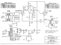
- on the unregulated bipolar PSU lines the last three capacitor is with high value of 330uF/450V , IMO so high capacitors values is OK but for some powerful tube amp , so I wonder maybe some mistake is done and the right value is only 33uF/450V or so ?
You can run very high value caps even with valve rectifiers if the first cap is small and followed by a decent choke - there is literally no limit on the size of the second and third caps. Can take a very long time for the power supply to come up to full voltage (think up to a minute).
- did stability performance will be improved if we add on each triode one grid stopper resistor ? , let`s say around 1K each .
- on the unregulated bipolar PSU lines the last three capacitor is with high value of 330uF/450V , IMO so high capacitors values is OK but for some powerful tube amp , so I wonder maybe some mistake is done and the right value is only 33uF/450V or so ?
Shoog
That is the beauty of a single zero in the loop
...really low distortion figures and high stability can be obtained without resorting to semiconductor 'helpers'.
Yes, I see what you mean.
Going back to the original topic of this thread, here's a refinement of the ECC82 CCDA with NFB for a linestage.
It's a 12AU7 Bootstrapped Pair with Shunt NFB. No MOSFETs. It does require those big cap values for infrasonic stability while still being flat to 20Hz, but it's easy to achieve. Ultrasonic stability is fine, because there isn't that much NFB applied. THD is predicted to be <0.01% with 1V rms out (1kHz).
It is inverting, though.
Last edited:
I'm not very familiar with this, but this circuit topology looks nice.
Basically combining the benefits of bootstrapping in this way and NFB to "modulate" the gain to the desired entity.
So then you have a so to say "all-tube" design.
I had to read for a moment to understand the role of C2: in practice, if I understand correctly, with that value it is almost like setting U1 with a CCS (with more amplification in U1), plus there is an improvement in the PSRR than standard CCDA. Then there is this stability role in LF you say ...
Well, from you simulations it seems that things improved overall than in the previous design. If I can fit a good MKP capacitor inside the box I could try the changes too...
If simulation can be believed, the constant current draw caused by both U1 and U2 drawing the same Ia does increase immunity to noise from the power supply. I simulated this circuit with a 330V raw B+ with a 2V peak AC sine wave at 120Hz, to simulate psu ripple. After that comes a CRCRC of 100uF--470R--680uF--470R--680uF. That drops 30VDC to feed 300V (as in the schematic of post #235).
The CRCRC completely suppressed the 2VAC ripple down to nothing. I assume the ripple suppression of the passive filter is helped by the CCDA constant current draw action combined with the bootstrapping of the plate load for U1.
In other words, the above circuit should have very good Power Supply Rejection Ratio (PSRR), which means you don't need to feed it with a fancy regulated B+. At these low signal levels and using indirectly heated triodes, you should be able to use an AC heater supply (6.3V or 12.6V). Cheap and easy! I like cheap 'n easy.
Just acomment: the anode and cathode now have a different AC, methinks, because of the bootstrap-feedback. And AC balance is at the heart if the Broskie balance draw amplifier. Only then the PS is silent. But I did not model it.
I'm not sure I understand.
By "have a different AC", can you tell me, AC what, exactly?
Gain? That can't be the case, because a cathode follower has about 0.95X gain due to nearly 100% NFB, while the common cathode stage has gain somewhere near the mu of the triode. Of course the gain of the first triode is also reduced by NFB, so that complicates things.
AC voltage signal swing? U2 is a cathode follower, so it should follow the voltage swing from the plate of U1.
I went back and read Broskie's CCDA article.
https://www.tubecad.com/2009/03/blog0161.htm
I don't see anything about AC current swings, just that the DC current draw from the first and second stages need to match.
I may have missed some things, though...
Last edited:
Could you maybe redraw the circuit for a slightly higher gain (ideal 3-4x) and the Vb + max 265V?
However, if the simulated features relate to the real world it would be good. Thanks.
I bring you also the schematic found on Broskie, here there is a very little difference between the two R of bootstrap, and it was after argumentated how to choose the right values:

https://www.tubecad.com/2012/10/blog0246.htm
However, if the simulated features relate to the real world it would be good. Thanks.
I bring you also the schematic found on Broskie, here there is a very little difference between the two R of bootstrap, and it was after argumentated how to choose the right values:
https://www.tubecad.com/2012/10/blog0246.htm
- Home
- Amplifiers
- Tubes / Valves
- A good route to a ECC82 preamp