because you are ?Why has no-one bothered to model this? 😉

Yep. It's currently a weekend project which I'm keeping under wraps as I'm not sure what I want to do with it. However finally I'm getting accurate results. For example, the question about if the cheeks are flatter, does it produce a lower SPL. I can answer yes, however it manipulates lower frequencies. Where you would expect, for example, 50hz to be omni directions on a polar plot, a rubanoide will have a void at 0degs.because you are ?
Oh im sorry i kind of made it less under wraps.. i hope you dont mind sorry 🙁
it also will tell you that the dip at 16khz +_ would be less with more flat *** cheeks. and yes the low end it likes it to be less flat more round... since it wont be moving as a cone/rigid paper if flat. breakup etc. rubas are fun but not ideal if you ask me 🙁 and having 2 coils spaced appart in the direction of listening area is not ideal either 🙁 then again its a driver that can cover a quite broad range. if done well🙂
it also will tell you that the dip at 16khz +_ would be less with more flat *** cheeks. and yes the low end it likes it to be less flat more round... since it wont be moving as a cone/rigid paper if flat. breakup etc. rubas are fun but not ideal if you ask me 🙁 and having 2 coils spaced appart in the direction of listening area is not ideal either 🙁 then again its a driver that can cover a quite broad range. if done well🙂
Last edited:
Wieder mal einen gebaut !
Er ist noch nicht perfekt, aber die ersten Töne haben mich überrascht.
Er ist noch nicht perfekt, aber die ersten Töne haben mich überrascht.
Very interesting thread. I would be interested in making a woofer. 40Hz to 1Khz would be ideal. Obviously the big issue seems to be distortion, but if I don't need very high frequency extension, I should be able to choose different material.
I know WrineX used foam board and managed to get decent low end performance. I am thinking about using prepreg carbon fiber since it should be relatively stiff and I don't need to worry about using too much epoxy. It should also be pretty good at keeping the coil in the gap.
Thoughts?
I know WrineX used foam board and managed to get decent low end performance. I am thinking about using prepreg carbon fiber since it should be relatively stiff and I don't need to worry about using too much epoxy. It should also be pretty good at keeping the coil in the gap.
Thoughts?
it think for real lows, one mmight need to make either something completely new, or use just a woofer. they are pretty good at the task 40-1khz 🙂
the ones i made had a huge downside max spl 🙁 they cant play near any woofers spl even a 5 inch one 🙁
the ones i made had a huge downside max spl 🙁 they cant play near any woofers spl even a 5 inch one 🙁
I am planning a 30 x 16 cm Rubanoid, which will be supported in the bass by 2 25cm woofers in a dipole housing (stacked).
Optionally, of course, high-frequency support.
This is my current plan, subject to change.

Optionally, of course, high-frequency support.
This is my current plan, subject to change.
Last edited by a moderator:
I've come inyo some 25x40x14mm n52 magnets and some 33cm long pieces of 25x10mm mild steel cold rolled bars. I intend a small (30cm) experimtal rubanoid motor. What's the best step-by-step way to construct the motor sides. Do I glue all the magnets to one bar then slide the other bar into place? Or do I slide each magnet one at a time into place between the bars then glue. Hoping someone that's been through this can give thie insight. (I will probably need to construct a jig to keep from losing digits. )
Hi cubby, this is the most tricky and dangerous part. Here is the translation of what wrote the late inventor :"Magnet assembly (the only difficulty is assembling the magnets and assembling the two motor halves once the magnets are assembled)
- Place the second flat bar, gently bring it closer to the glued magnets. When it is in place, slide it in with a wooden mallet.
Assembling the motor halves is quite difficult because the magnetic force is intense and you can easily crush your finger and have It was difficult to remove it.
I used softwood wedges and glued the air gap shims on them. Then I rolled one half of the engine onto the other with aluminum rollers. When the engine halves were in place, I removed the rollers and then removed the wooden wedges with an aluminum blade.
(This is the hardest and most dangerous part to do. Keep away from children and wear thick gloves.)" Just do it and good luck !
- Mark the orientation of the magnets. when assembling they must repulse and not attract them to each other.
- Secure a flat bar in a vice with two wooden L-shaped pieces to prevent a magnet from sticking to the vice (otherwise, removing it is almost impossible). Don't forget the location of the 10mm aluminum square at the beginning of the flat bar.
- Slide one magnet onto the flat bar and glue it with super glue and wait for it to dry.
- Slide another magnet onto it, bring it closer with an aluminum joint clamp. When the two are joined, glue it with super glue.
- Proceed in this way along the entire length.
- Place the second flat bar, gently bring it closer to the glued magnets. When it is in place, slide it in with a wooden mallet.
Assembling the motor halves is quite difficult because the magnetic force is intense and you can easily crush your finger and have It was difficult to remove it.
I used softwood wedges and glued the air gap shims on them. Then I rolled one half of the engine onto the other with aluminum rollers. When the engine halves were in place, I removed the rollers and then removed the wooden wedges with an aluminum blade.
(This is the hardest and most dangerous part to do. Keep away from children and wear thick gloves.)" Just do it and good luck !
Hi All,
I became aware of rubenoides in Jan, and was lucky enough to see this forum and also the fantastic youtube videos that many of you have posted - outstanding stuff!
also expensive stuff....lots of steel, aluminium, magnets (only ferrites so far) and enough types pf paper to open a stationary shop, plus a UMIK-1 - but i now have some prototypes which. although not perfect yet, are revealing things that my normal speakers just don't resolve (and they are pretty well regarded speakers) - I am now pretty committed to building a "final" set
I am not in a mad hurry, as i am just enjoying the prototypes ( i will share photos and descriptions a little later)... but as i move towards a final version, I have a series of questions which I am hoping you folks can help me with, and also a series of observations that might be of interest
My hope is that we can resurrect the "FAQ/hints" posts which Sergui2009 kicked off, and provide some options for novice builders (am i the only one? you guys seem very advanced compared to my efforts)
anyway, i just wanted to briefly introduce myself, and let you know how much of an inspiration you have all been so far, and hope that you will continue to be in the future
Simon
Thanks to WrineX for already giving some encouragement – here goes with my postings……
I will do a proper intro a little later, but for now I wanted to share an observation.
My prototype motor is 2 x 360 high set of mild steel pole pieces, enclosing a stack of 11 ferrites, each 50x25x10mm. so an internal magnet stack height of 275mm

I typically made the coils (0.15mm, hand wound) the same height as the magnets
But as my intention is to go 500mm, or even 700mm high membranes, this does not really scale easily, as the coil, even if I could make it nicely, would not have many turns
So I tried to run a design experiment.
I made 4 identical membranes – 140gsm canson, same method of fixing the coil and combining the membranes - I focused on making the membranes identical rather than making them sound /measure the best, so used things like double-sided tape etc.
The only difference was the height of the coil, and also the variation in measured DC impedance
so to summarise - a coil half the height of the membrane / magnet stack performed as well, if not better, than coils which were sized closer to the membrane height/magnet stack

I have deliberately removed the scales etc on the graph, as the experiment was to compare traces, not optimise the response etc. the SML coil is the highlighted one, and pretty clearly (at least to me) performs best
Absolutely not the result I expected – I actually ran the result twice, a week apart and on both left/right motors, and the results were consistent
So right now, it looks like size is important, but despite what you might have heard, bigger is not better
I am away over easter, but when I get back, I will see how small I can go, but for that I will need wider pole pieces, as the coil width is already around the same width as the mild steel (6mm)
The implications, I believe go beyond just the coil and I also want to start looking at the motor – if the best sound is using only half the stacked magnets then am I better halving the stack but using magnets twice the power, for example (I suspect its not as linear as that, but you get the idea….)
Of course, across the various posts, people are using different height coils, but from what I have seen, they all correspond broadly to the height of the membrane, so maybe this is something new?
Its possible that my valve amps like a higher resistance, so that might account for some of this, as the smallest height has the highest resistance, so i might redo that one, but even so, I dont think it would explain away what the graph is telling me
I would love to know anyone's thoughts, and whether anyone with a more technical background in these matters can formulate a reason for what I am seeing
thanks for reading 🙂
I will do a proper intro a little later, but for now I wanted to share an observation.
My prototype motor is 2 x 360 high set of mild steel pole pieces, enclosing a stack of 11 ferrites, each 50x25x10mm. so an internal magnet stack height of 275mm
I typically made the coils (0.15mm, hand wound) the same height as the magnets
But as my intention is to go 500mm, or even 700mm high membranes, this does not really scale easily, as the coil, even if I could make it nicely, would not have many turns
So I tried to run a design experiment.
I made 4 identical membranes – 140gsm canson, same method of fixing the coil and combining the membranes - I focused on making the membranes identical rather than making them sound /measure the best, so used things like double-sided tape etc.
The only difference was the height of the coil, and also the variation in measured DC impedance
- Coil 1: SML 8.7ohm – 140mm high
- Coil 2: MED 8.1ohm – 197mm high
- Coli 3: LG 8.4ohm – 240mm high
- Coil 4 : XLG 8.0ohm – 297mm high
so to summarise - a coil half the height of the membrane / magnet stack performed as well, if not better, than coils which were sized closer to the membrane height/magnet stack
I have deliberately removed the scales etc on the graph, as the experiment was to compare traces, not optimise the response etc. the SML coil is the highlighted one, and pretty clearly (at least to me) performs best
Absolutely not the result I expected – I actually ran the result twice, a week apart and on both left/right motors, and the results were consistent
So right now, it looks like size is important, but despite what you might have heard, bigger is not better
I am away over easter, but when I get back, I will see how small I can go, but for that I will need wider pole pieces, as the coil width is already around the same width as the mild steel (6mm)
The implications, I believe go beyond just the coil and I also want to start looking at the motor – if the best sound is using only half the stacked magnets then am I better halving the stack but using magnets twice the power, for example (I suspect its not as linear as that, but you get the idea….)
Of course, across the various posts, people are using different height coils, but from what I have seen, they all correspond broadly to the height of the membrane, so maybe this is something new?
Its possible that my valve amps like a higher resistance, so that might account for some of this, as the smallest height has the highest resistance, so i might redo that one, but even so, I dont think it would explain away what the graph is telling me
I would love to know anyone's thoughts, and whether anyone with a more technical background in these matters can formulate a reason for what I am seeing
thanks for reading 🙂
The coils should be slightly longer than the pole plates and located in the center of the magnets. Why are the pole plates longer than the magnets? So, was the short coil tested in the longer drive? Regards
Hi Ruba1, so grateful for the reply
to confirm current dimensions - the pole plates/magnets are (depending on your orientation)
*horizontally - magnets and steel both 50mm
*vertically - 360mm steel poles/275mm magnets
the extended section above the magnets (effectively 2 "prongs" of 42.5mm) is where each side is secured and inserted into the top housing - this kinda follows the various postings here - a great visual example is this one from Solhaga, back here: https://www.diyaudio.com/community/...peaker-of-a-different-kind.69450/post-5483517:

My suspicion os that when you refer to length, its the horizontal you are talking about? in that case, the length of the magnets and the pole peices are both the same, at 50mm
I might be misusing the term motor, pole plate etc. so that might also explain my confusion? if so, apologies
please see image below of my design, where i have made the top housing transparent purple, so you can see the prongs entering the housing:

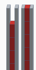
what i interpret from your comments can be shown pictorially below (magnets in red, mild steel in grey)
on the left is what i have now
in the middle is what you seem to be recommending?
on the right is a rough view of how the coil is currently located
(obviously, i am only showing one side of the motor here 🙂)

Again, really appreciate you taking the time to respond - just not sure my initial post was clear enough? really hope this one helps refine things
to confirm current dimensions - the pole plates/magnets are (depending on your orientation)
*horizontally - magnets and steel both 50mm
*vertically - 360mm steel poles/275mm magnets
the extended section above the magnets (effectively 2 "prongs" of 42.5mm) is where each side is secured and inserted into the top housing - this kinda follows the various postings here - a great visual example is this one from Solhaga, back here: https://www.diyaudio.com/community/...peaker-of-a-different-kind.69450/post-5483517:
My suspicion os that when you refer to length, its the horizontal you are talking about? in that case, the length of the magnets and the pole peices are both the same, at 50mm
I might be misusing the term motor, pole plate etc. so that might also explain my confusion? if so, apologies
please see image below of my design, where i have made the top housing transparent purple, so you can see the prongs entering the housing:
what i interpret from your comments can be shown pictorially below (magnets in red, mild steel in grey)
on the left is what i have now
in the middle is what you seem to be recommending?
on the right is a rough view of how the coil is currently located
(obviously, i am only showing one side of the motor here 🙂)
Again, really appreciate you taking the time to respond - just not sure my initial post was clear enough? really hope this one helps refine things
Attachments
Okay, misunderstanding. So, the coils are in the middle of the pole plate. With the short coil ends, with a radius, there may be lateral movement. I don't know if you can hear that. Regards
again, thanks,
i remember an earlier post- might have been WrineX? - that seems to relate. you are saying that keeping the radius of the coil outside the magnet field would mean movement would be reduced/removed in the lateral plane. right
so something like either of these (the 2nd is maybe the only one that would work for this):

if so, that seems very logical and worth me trying, to see if its audible - thanks👍
i remember an earlier post- might have been WrineX? - that seems to relate. you are saying that keeping the radius of the coil outside the magnet field would mean movement would be reduced/removed in the lateral plane. right
so something like either of these (the 2nd is maybe the only one that would work for this):
if so, that seems very logical and worth me trying, to see if its audible - thanks👍
- Home
- Loudspeakers
- Planars & Exotics
- A DIY Ribbon Speaker of a different Kind