Here is a zipped download of (I think) all files needed for this. Parts lists, Gerber files, Schematic, stl files for 3D printing, notes on each.
link: https://libinst.com/MEMSmic/Construction Files For MEMS mic.zip
link: https://libinst.com/MEMSmic/Construction Files For MEMS mic.zip
Thanks for the detailed write-up and valuable data, @bwaslo.
I built a similar mic a few years ago with a different chip (SPM0687LR5H-1). I don't have a 'real' reference mic to calibrate it against, so I set up simulations in ABEC3 to approximate the acoustic contribution of the bare chip body and of the complete mic in free space. The results agree pretty well with my old Cross-Spectrum calibrated EMM-6, but the calibration was done quite a while ago so I don't know how accurate it is now[1].
I set up new simulations based on your mic design in order to check the validity of my simulation technique (thanks again for the measurements!). Here's the 0° free field response, derived from the simulation results along with the datasheet curves (green curve; click to enlarge):
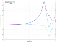
Purple is data I extracted from your measurement in post #5. The agreement is quite good up to almost 40kHz, but there's a considerable difference above that—especially at ~55kHz. The datasheet curve seems to be the source of most of the difference as it has a large dip in that region.
1: My EMM-6 also developed some problem which results in inaccurate LF response (leaky capsule?). Doesn't seem to significantly affect the HF response.
I built a similar mic a few years ago with a different chip (SPM0687LR5H-1). I don't have a 'real' reference mic to calibrate it against, so I set up simulations in ABEC3 to approximate the acoustic contribution of the bare chip body and of the complete mic in free space. The results agree pretty well with my old Cross-Spectrum calibrated EMM-6, but the calibration was done quite a while ago so I don't know how accurate it is now[1].
I set up new simulations based on your mic design in order to check the validity of my simulation technique (thanks again for the measurements!). Here's the 0° free field response, derived from the simulation results along with the datasheet curves (green curve; click to enlarge):

Purple is data I extracted from your measurement in post #5. The agreement is quite good up to almost 40kHz, but there's a considerable difference above that—especially at ~55kHz. The datasheet curve seems to be the source of most of the difference as it has a large dip in that region.
1: My EMM-6 also developed some problem which results in inaccurate LF response (leaky capsule?). Doesn't seem to significantly affect the HF response.
bmc0,
"Here's the 0° free field response, derived from the simulation results along with the datasheet curves (green curve".
I'm a little unclear -- your simulation is for the free-field pressure buildup of the mounting arrangement (chip package inset on a 6mm disc at end of a tube), with the chip specs? The match isn't bad if so, other than up above the resonance peak, hard to say what's going on up there. My eq circuit even has an added LPF to bring that upper area down a bit for a bit of extension.
My measurement is based on the B&K and ACO reference 1/4" mics. Their calibration was done for pressure response by electrostatic activation, then corrected per B&K provided free-air correction curves (which are taken on faith, I can't calculate those). Can you sim do the B&K 4135 capsule dimensions to see if it comes up with correction curves similar to B&K's for pressure to free-air response?
Yes. There are two simulations involved—one for the bare chip and one for the completed microphone assembly. The first is needed, of course, because the datasheet gives the free-field response rather than the pressure response. The influence of the bare chip body is replaced by that of the complete assembly when mounted, so the former must be removed from the datasheet curve before applying the correction for the latter.I'm a little unclear -- your simulation is for the free-field pressure buildup of the mounting arrangement (chip package inset on a 6mm disc at end of a tube), with the chip specs?
Here's the free-field response, extracted directly from the datasheet:
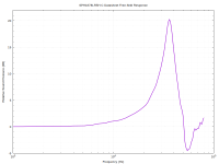
I merged the audio band (up to 20kHz; log frequency scale) and ultrasonic (up to 80kHz; linear frequency scale) data. You can see that there's a considerable dip around 55kHz which is not present in your measurements.
Here are the simulated free-field corrections for the bare chip (purple) and complete assembly (green):

Solid is 0°, dashed is 45°, and dotted is 90°. The mic chip's pressure response should then be approximately the datasheet response minus the solid purple curve shown above. Then, one of the green curves can be applied in order to get the predicted free-field response of the complete assembly for the desired angle of incidence.
Regarding the difference above resonance: One thing that I did not include in these simulations is the influence of the radiation impedance on the mic's cavity resonance. No idea how significant that might be. Other than that, I have no idea what would account for the error.
I can try. That simulation will be slightly more complicated to set up because of the large diaphragm size relative to the wavelength. I'll have to come up with a weighting function to account for the nonuniform diaphragm motion.Can you sim do the B&K 4135 capsule dimensions to see if it comes up with correction curves similar to B&K's for pressure to free-air response?
There is also some question of how exactly Knowles measured the chip. Given the height of the resonant peak, I assumed it was by dangling a bare chip on thin wires (the only approach of mine that matched the resonant peak). But they could have had some support holding the chip that didn't interfere with the peak but caused variations up higher in frequency.
Or another possibility is chip consistency maybe isnt so great above the resonance, or perhaps the Knowles measurement was done on an early sample. It would seem unlikely that error in B&K's free field correction curve would so nicely counter a dip in the Knowles curve.
Or another possibility is chip consistency maybe isnt so great above the resonance, or perhaps the Knowles measurement was done on an early sample. It would seem unlikely that error in B&K's free field correction curve would so nicely counter a dip in the Knowles curve.
In case you haven't run into it, you can get B&K's freefield correction curves via their Microphone Viewer software (free download), https://www.hbkworld.com/en/about/news/2022/microphone-viewer
WRT microphone calibrations; There is a good relevant article attached on Page 12+. They compare theoretical calculations to measured results. There is also another article I may be able to find where some obsessives at The JIS compaired measurements to theory on the standard microphones. The departures were pretty small. The other article refers to reciprocity to 200 KHz. Not hapening with MEMs but the acoustic issues should be of interest.
Attachments
I was wondering about that when setting up the simulations for my mic as I couldn't find any authoritative info (from Knowles or otherwise). Perhaps I should try contacting Knowles to see if they'll actually tell me anything...There is also some question of how exactly Knowles measured the chip.
I can't imagine the error is in the B&K correction curves; surely someone would have noticed a ~12dB error sometime in the last 60 years 😉
Most likely, the explanation is either error in my simulation or something about Knowles' measurement procedures. Perhaps Knowles doesn't consider accuracy of the datasheet curves beyond 30kHz to be terribly important since that region is so sensitive to the mounting arrangement.
Here's a basic attempt to reproduce the B&K correction curves for the 4135 capsule (plus 2619 preamplifier) without its protection grid.
First, some images of the model (axisymmetric). Full view:

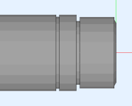
Close-up of capsule (side view):
Close-up showing the diaphragm:
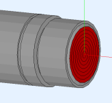
Some of the dimensions are just eyeballed as the dimensional drawings don't specify everything (the exact unsupported diaphragm diameter is not given, for example).
As expected, using a weighting function to account for the nonuniform diaphragm motion is important. Here are the results with no weighting (i.e. assuming uniform axial motion):
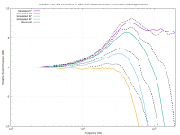
Not a great match.
At least at lower frequencies (where the pressure is relatively uniform), I figured it was probably reasonable to assume a catenary shape for the diaphragm. According to the cutaway drawings I can find, the backplate doesn't quite extend to the edge of the diaphragm, so I further reduced the weighting of the outermost segment. Here are the results using this modified catenary weighting:
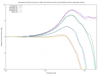
Much better, but not quite perfect. Nonuniform pressure over the diaphragm surface at high frequencies probably explains at least some of the remaining error.
Note: the measured correction curves were extracted from this B&K handbook (fig. 6.13, page 53).
First, some images of the model (axisymmetric). Full view:

Close-up of capsule (side view):

Close-up showing the diaphragm:

Some of the dimensions are just eyeballed as the dimensional drawings don't specify everything (the exact unsupported diaphragm diameter is not given, for example).
As expected, using a weighting function to account for the nonuniform diaphragm motion is important. Here are the results with no weighting (i.e. assuming uniform axial motion):

Not a great match.
At least at lower frequencies (where the pressure is relatively uniform), I figured it was probably reasonable to assume a catenary shape for the diaphragm. According to the cutaway drawings I can find, the backplate doesn't quite extend to the edge of the diaphragm, so I further reduced the weighting of the outermost segment. Here are the results using this modified catenary weighting:

Much better, but not quite perfect. Nonuniform pressure over the diaphragm surface at high frequencies probably explains at least some of the remaining error.
Note: the measured correction curves were extracted from this B&K handbook (fig. 6.13, page 53).
Wow, actually quite good, I'd say. Given that the actuator response won't be exactly equal to the pressure response. I believe I read that their correction curve takes that into account (by being derived by comparing reciprocity measurement to actuator response)
That's correct according to the B&K Microphone Handbook (be1447). However, it also states that the actuator correction is insignificant for microphones smaller than 1/2" due to their high diaphragm impedance. A few actuator correction curves for 1" and 1/2" capsules are given, but they only go up to 20kHz. I wonder if the difference is still insignificant at 100kHz for a 1/4" capsule.I believe I read that their correction curve takes that into account
Another major Bill Waslo contribution to the diy audio world. Have you seen this?
https://hackaday.io/project/185762-mems-based-iepe-powered-instrumentation-microphone
https://hackaday.io/project/185762-mems-based-iepe-powered-instrumentation-microphone
Should anyone be building one of these, I have some spare SLA 3D printed mic chip mounting parts I can spare (at cost of a self-addressed postpaid envelope). Several 3DP parts for the tube mounts as well, and some of the capacitor boards. Drop me a PM if interested.


Very cool Bill.
I have a lot of reading to do. And some thinking never really thought about the effects of the microphone case altering the frequency response. But now I have a whole lot more to consider. I might try and set up a multi measurement point Klippelish setup. Try and make the measurement cycles faster. I have a few Class 1 mics that I can use to calibrate via the reciprocity method mentioned above. Lots of great information here.
I have a lot of reading to do. And some thinking never really thought about the effects of the microphone case altering the frequency response. But now I have a whole lot more to consider. I might try and set up a multi measurement point Klippelish setup. Try and make the measurement cycles faster. I have a few Class 1 mics that I can use to calibrate via the reciprocity method mentioned above. Lots of great information here.
I was considering buying a XLR mic since I only have a umik1. And find your project really intresting.
Uncalibrated mic seesm already very good. But Where I am a bit lost is for phase. I know that some mics have a calibration data for phase. Did you look into this ?
Can we just omit this? (I guess that for passive crossover you dont't realy care because your mic will shift the phase the same way. But if you want to do unwrap the phase and do FIR, i'm not realy sure of what we need ...
Check out https://www.diyaudio.com/community/threads/a-diy-mems-measurement-microphone.417231/post-7782052 .
In the 3rd graph you'll see the phase curve with that dB magnitude curve. Except at very expanded scale for the right angle axis, all the mics phase response will look much the same, at least below ~40kHz. And for good reason -- the magnitude curves are all quite similar (and flat, note the dB/div scale on the graphs) Like essentially all omni mics, these are minimum phase transducers so the phase curve can be determined by the mag curve and will also be quite similar to the other phase curved (and particularly flat when corrected for time of flight delay).
In the 3rd graph you'll see the phase curve with that dB magnitude curve. Except at very expanded scale for the right angle axis, all the mics phase response will look much the same, at least below ~40kHz. And for good reason -- the magnitude curves are all quite similar (and flat, note the dB/div scale on the graphs) Like essentially all omni mics, these are minimum phase transducers so the phase curve can be determined by the mag curve and will also be quite similar to the other phase curved (and particularly flat when corrected for time of flight delay).
Ok I see. So that's maybe why some manufacturers do not give the phase calibration.
I had a look at the datasheet and they also give the typical fr and phase curves.
Have several questions:
- What the reason for which you made an electrical equalization rather than just make a calibration file ? This seems to me easier.
It also reduce the size of the PCB that can then be put inside the mic. If used with a phantom supply you don't need anything else.
- I have seen that you tried to mount the MEMS on PCB and this was lowering resonant frequency. Does it affect the FR on the 20-20K range ?
They are specifying a 0.6 to 1mm hole. And was thinking that this hole. should not affect the FR (Or the FR given in the datasheet was taking care of this)
JLPCB can have the mems in stock: about 9 euros for 27 pieces so very chip(we can't take less). And can solder them on PCB. They also have flex PCB.
They rate the solder technic "difficult" so maybe they can't do it on flex if there is some constraints on this.
We will need to solder wires on the flex PCB but it should be easier than on mems.
I will try to make a project and see how many they charge. It seems 2 euros for the standard flex pcb So I need to check this.
They also offer 0.8mm fr4 for 2 euros and 0.6mm for 8 dollar 0.4 is much more expensive.
It is for 5 PCB of 100*100mm so we can fit a lot on it. If done right I think we can we can make 5x both mic and MEM PCB on the same board.
So it would give a mounted MEMS board and mic PCB for something like 2 euros each.(if no on board equalization)
Of course all this needs to be verified.
If this is the case, it would be possible to make a kind of "KIT" for peaple that want to build one.
- Home
- Design & Build
- Equipment & Tools
- A DIY MEMS Measurement Microphone