To the best of my knowledge standard LLC smps is typically protected against OC by either: Split-capacitor and clamp-diodes to rails or voltage-measurment of the capacitor-voltage.
The Split-capacitor-diode-idea is simple but limits the voltage over the caps and for some designs that may be a problem?
The voltage-over-capacitor-reading is proven and tested, but requires a high-voltage-capacitor to work?
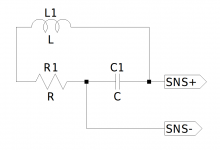
So late last night i got en idea: if the LLC is implemented with a seperate series-inductor we can directly measure the current in this by adding a single (isolated) winding and putting a suitable resistor across the single winding. Voltage over the resistor is then a true reading of the current in the LLC-loop.
The voltage could easily be scaled and fed to the CUR-limit input of controllers like L6599.
Is this an old idea? - i could not find anything on google, but that is probably because I dont know the correct words to search for.
I have a working LLC on the workbench and Im tempted to test the idea, but let me hear your thoughts.
Kind regards TroelsM
The Split-capacitor-diode-idea is simple but limits the voltage over the caps and for some designs that may be a problem?
The voltage-over-capacitor-reading is proven and tested, but requires a high-voltage-capacitor to work?
So late last night i got en idea: if the LLC is implemented with a seperate series-inductor we can directly measure the current in this by adding a single (isolated) winding and putting a suitable resistor across the single winding. Voltage over the resistor is then a true reading of the current in the LLC-loop.
The voltage could easily be scaled and fed to the CUR-limit input of controllers like L6599.
Is this an old idea? - i could not find anything on google, but that is probably because I dont know the correct words to search for.
I have a working LLC on the workbench and Im tempted to test the idea, but let me hear your thoughts.
Kind regards TroelsM
Haven't you just described a current transformer and as such doesn't the burden resistor interfere with the value/operation of the series inductance.
Haven't you just described a current transformer and as such doesn't the burden resistor interfere with the value/operation of the series inductance.
Yes, it is definitely a current-transformer, but I dont think the burden resistor have to interfere much. - it should be simple to simulate. I'l fire up LtSpice when I get the time.
My theory is rusty but from a energy-point of view: the current in the coil is typically 5-10A in my example. We want a few mA and 2-5V for triggering the OC in the driverchip.
The disturbance should be equal to the energy-ratio from LLC-loop to OC-control. ( does that make sense?)
EDIT: the "similar threads" below actually suggested something that is probably close to my idea QCS PLX series:
http://bee.mif.pg.gda.pl/ciasteczkowypotwor/SM_scena/QSC/QSC_PLX_Series_Service_Manual.pdf
Look at the schematic for the PSU and locate the resonant inductor L6. There is a "sense-vinding" on L6 to trigger STBY.
Kind regards TroelsM
Last edited:
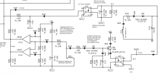
Schematic of the LLC resonant converter, based on a SOI HB power module... | Download Scientific Diagram
This hints the idea of measuring the current in the primary resonant circuit with a current transformer. There is no separate inductor so they do not use a measurement winding on a separate inductor but a dedicated current transformer.
I believe that MorbidFractal once more is right. The "burden resistor" on the measurement winding should be translated into a resistance in the line where you wish to measure the current and that affects your resonance in the LLC-circuit. I am sure MorbidFractal is much better in such principles than I.
The gain with your idea would be to avoid a dedicated current transformer and instead use an extra measurement winding on an existing inductor, if it works. A small economical gain but nevertheless a gain.
It's not something I have looked very hard at but there is a lossless sensing mechanism found in VRMs where a current sense signal is extracted directly from the phase buck inductor using an RC network. It is meant to recreate a facsimile of the voltage across the ESR of the inductor across the capacitor by selection of circuit time constants.
If your sense winding reproduces the voltage across the primary in a faithful manner then it would seem to be possible to implement a similar scheme. This would appear to be what QCS has done and what you are proposing. Nominally the secondary is only lightly loaded and you presumably could introduce gain based on turns ratio.
I would be inclined to read up on VRM lossless current sensing for further information and sums.
...
Attachments
Maybe a bit late but it might be helpful for others:
Behringer implemented a peak current detecting circuit in LLC SMPS of the B815neo, B812neo and B912neo series. I do not attach the schematics because they mention copyright, but you can easily find them for the Behringer B912neo.
The circuit looks very similar to the one of QSC, except Berhinger added a latch circuit that is triggered and prevents the PWM generator from starting unless you did a full power cycle of the unit.
Therefore they omitted the average overcurrent protection (at least I could not see any).