I wondered whether to start a new thread for this or tag this on to a (very) old thread. I've decided on new but will cross link the other to this as it touched on the subject...
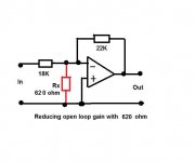
So what's this all about. Well a comment in the linked thread by Nelson Pass grabbed my attention. Nelson commented that when using opamps in low or unity gain configurations that he liked to "throw" some of the available open loop gain away in the interests of "stability" as many opamps under unity gain are running close to their stability margin. The result of doing that was a subjective improvement in sound quality.
The whole of that thread is interesting reading and so I would recommend anyone reading this to go and have a read at the other one too.
http://www.diyaudio.com/forums/solid-state/6558-opamp-inverting-input-sounds-better.html
-----------------------------------------------------------------------------------------------------------------------------------------------
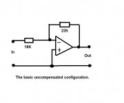
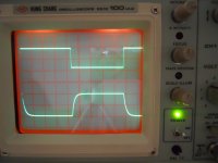
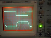
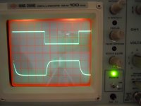
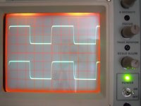
There are 4 groups of shots below, each with the relevant circuit. The opamp was the OPA134 in all cases running on -/+12 volts. The input frequency was 40Khz and the circuit tested at two levels, first 10 volts pk-pk output, and then the input was reduced by 40db to give 10 mv pk-pk output. This was done as non-linearities and differences can occur as levels increase/decrease.
Given a choice, which "compensation" technique would offer the best results do you think... and I don't know, I haven't tried this for real. I was wondering whether it would be worth trying on my amp which uses two opamps in inverting configuration.
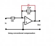
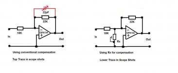
You'll notice that the "normal" method with the 22pF cap is very very similar to the one with no cap and a value of 620 ohms for Rx. Would it be subjectively better ? Or might a combination of the two techniques give the best subjective results ?
I don't even know what you call this method. I've seen it referred to as "increasing the noise gain" and it's a well known technique (with lower values of Rx) for increasing noise/distortion levels of the best opamps to make those parameters more easily measurable.
So what's this all about. Well a comment in the linked thread by Nelson Pass grabbed my attention. Nelson commented that when using opamps in low or unity gain configurations that he liked to "throw" some of the available open loop gain away in the interests of "stability" as many opamps under unity gain are running close to their stability margin. The result of doing that was a subjective improvement in sound quality.
The whole of that thread is interesting reading and so I would recommend anyone reading this to go and have a read at the other one too.
http://www.diyaudio.com/forums/solid-state/6558-opamp-inverting-input-sounds-better.html
-----------------------------------------------------------------------------------------------------------------------------------------------
There are 4 groups of shots below, each with the relevant circuit. The opamp was the OPA134 in all cases running on -/+12 volts. The input frequency was 40Khz and the circuit tested at two levels, first 10 volts pk-pk output, and then the input was reduced by 40db to give 10 mv pk-pk output. This was done as non-linearities and differences can occur as levels increase/decrease.
Given a choice, which "compensation" technique would offer the best results do you think... and I don't know, I haven't tried this for real. I was wondering whether it would be worth trying on my amp which uses two opamps in inverting configuration.
You'll notice that the "normal" method with the 22pF cap is very very similar to the one with no cap and a value of 620 ohms for Rx. Would it be subjectively better ? Or might a combination of the two techniques give the best subjective results ?
I don't even know what you call this method. I've seen it referred to as "increasing the noise gain" and it's a well known technique (with lower values of Rx) for increasing noise/distortion levels of the best opamps to make those parameters more easily measurable.
Attachments

Interesting.
Wondering if the output Z of the sig gen plays a role in this? (seems not, but...)
Also could you tweak the pf and get the same looking result?
Also why would a lower R result in over compensation??
Was there a load on the opamp?
I have no answers, btw...
_-_-bear
Wondering if the output Z of the sig gen plays a role in this? (seems not, but...)
Also could you tweak the pf and get the same looking result?
Also why would a lower R result in over compensation??
Was there a load on the opamp?
I have no answers, btw...
_-_-bear
signal generator terminated correctly?
instead of scope probe use resistor divider with 50ohm characteristic impedance loading the opamps output and set scope to 50ohm mode, use BNC soldered to output of divider. I don't believe scope probes on switching transients.
instead of scope probe use resistor divider with 50ohm characteristic impedance loading the opamps output and set scope to 50ohm mode, use BNC soldered to output of divider. I don't believe scope probes on switching transients.
Generator has a 50 ohm output impedance.
The top trace is measured across "In" on the circuit.
No load on the opamp output other than 10/1 probe.
Tweaking the compensation cap gives the same "looking" result at a given frequecy. You can see that in circuit 2 and circuit 4.
Quote // "I don't believe scope probes on switching transients."
If it were high frequency and high current/inductive loading etc then I would agree but I don't see a problem here.
You are not compensating anything by adding a resistor between the inverting and non-inverting input. In fact you are adding a capacitor between these inputs. Just look at your scope probe specifications to see how large this capacitor is.
One question to ask is to what extent is the 'ringing' seen in the first plot due to verging on instability, rather than some approximation of brick-wall filtering of a square wave. Have you measured the frequency response? Does it have a significant peak, or merely a sudden drop?
Putting a resistor between the inputs will shunt the stray capacitance there and so reduce loop HF phase shift. It may also help equalise the source impedance seen by the two inputs which may increase open loop linearity, while at the same time reducing loop gain which will reduce closed-loop linearity. The net result might be a reduction in higher order products from feedback mixing.
Putting a resistor between the inputs will shunt the stray capacitance there and so reduce loop HF phase shift. It may also help equalise the source impedance seen by the two inputs which may increase open loop linearity, while at the same time reducing loop gain which will reduce closed-loop linearity. The net result might be a reduction in higher order products from feedback mixing.
You are not compensating anything by adding a resistor between the inverting and non-inverting input. In fact you are adding a capacitor between these inputs. Just look at your scope probe specifications to see how large this capacitor is.
The scope probes don't come into contact with the opamp input pins, only the output pin and the input to the circuit (the generator output)
One question to ask is to what extent is the 'ringing' seen in the first plot due to verging on instability, rather than some approximation of brick-wall filtering of a square wave. Have you measured the frequency response? Does it have a significant peak, or merely a sudden drop?
Putting a resistor between the inputs will shunt the stray capacitance there and so reduce loop HF phase shift. It may also help equalise the source impedance seen by the two inputs which may increase open loop linearity, while at the same time reducing loop gain which will reduce closed-loop linearity. The net result might be a reduction in higher order products from feedback mixing.
Yes there is a peak. With the output set to 10 volts pk/pk midband as the frequency rises from around 600khz there is a gentle rise followed by a sharp "switch" to around 17volts pk pk output at around 870khz followed by a roll off. The point at which this increase occurs is sudden and there is hysteresis in that the frequency has to be reduced a little before it "recovers" back down.
I'm going to post some more shots that might be of interest shortly...
Interesting. Hysteresis may mean that your loop gain Bode plot has a little loop in it somewhere near the (-1,0) point so you may even be only conditionally stable. Reducing the op-amp gain will bring you down into the unconditional stability region. You might find that there is a critical value of resistor between inputs which turns it into an oscillator, not because it is adding capacitance but because it drags the Bode plot loop right on top of the (-1,0) point.
I set up two OPA134's as shown in the circuit below.
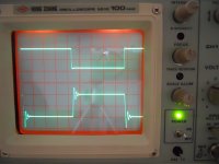
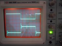
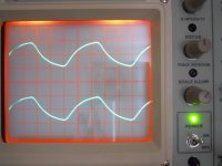
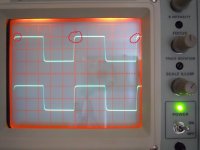
The beehive trimmer cap was adjusted for good compensation of the first opamp (top scope trace in all following shots) at 40 Khz and 10mv pk pk output.
The resistor Rx on the second opamp was adjusted to give an identical waveform compared to the conventionally compensated opamp above. The value of Rx was 1950 ohms. The traces could be overlaid with no difference showing at 10 mv pk-pk output.
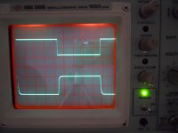
These shots show the output at 40 khz and 10 mv pk-pk and also at 1Mhz and 10 mv pk-pk. As can be seen the results appear identical.
The beehive trimmer cap was adjusted for good compensation of the first opamp (top scope trace in all following shots) at 40 Khz and 10mv pk pk output.
The resistor Rx on the second opamp was adjusted to give an identical waveform compared to the conventionally compensated opamp above. The value of Rx was 1950 ohms. The traces could be overlaid with no difference showing at 10 mv pk-pk output.
These shots show the output at 40 khz and 10 mv pk-pk and also at 1Mhz and 10 mv pk-pk. As can be seen the results appear identical.
Attachments
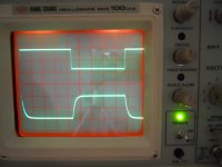
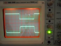
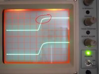
And here is the large signal performance at 40 khz and 10 volts pk-pk.
The non linearity in the C compensation can be seen. The second shot is a detail of the non linearity. This was clearly seen by eye even at much lower frequencys where the eye seems to winkle out detail that the camera doesn't resolve. At 40Khz it's obvious though.
The compensation (is that the right word ?) when done by Rx doesn't give this error.
Attachments
the usual way of applying "noise gain compensation" is to use series RC so the loop gain reduction doesn't cost as much low frequency (audio) performance
the RC time constant sould be set so that the closed loop (noise) gain flattens out before the gain intercept
looking up the series: http://www.analogzone.com/acqt0814.pdf could useful
the RC time constant sould be set so that the closed loop (noise) gain flattens out before the gain intercept
looking up the series: http://www.analogzone.com/acqt0814.pdf could useful
a warning on non-inverting mode - you may need a input bypass C to AC gnd the noise gain network to prevent input cmrr AC perfromance from interacting with loop stability
this can be part of a RF/EMI rejection filter
this can be part of a RF/EMI rejection filter
a warning on non-inverting mode - you may need a input bypass C to AC gnd the noise gain network to prevent input cmrr AC perfromance from interacting with loop stability
this can be part of a RF/EMI rejection filter
I wouldn't like to say one way or the other on that...
Have a read at page 13,
http://www.ti.com/lit/ds/symlink/opa1611.pdf
The resistor on its own is the recommended technique for testing with ultra high performance opamps.
thats for testing only
thats for deliberately making audio frequency perfromance worse to see anything at all with your distortion analyzer
if you want to use the technique to stabliize decompensated op amps or add stability margin with C load there's no reason to want to ruin audio frequency performance by shunting away gain all the way down to DC
Yes I realise that... and that doing this degrades the noise and distortion properties... but the big question is whether it's subjectively better.
Did you read Nelson posting in the link at the top,
Post in question is here,
http://www.diyaudio.com/forums/solid-state/6558-opamp-inverting-input-sounds-better.html#post67880
JCX was ahead of me; the use of Rx allows to set for distortion gain in test setups. THD+N has come to the level in opamps where most distortion analyzers cannot cope anymore.
@Mooly
The question whether it would be subjectively better is fallacious imo, without defining for what purpose. In order to create an effects box, it might be interesting, e.g. for distorting a guitar, or to emulate a WAVAC without spending 350K. In audio, I think it is a safe bet that all distortions that are not there make it better.
vac
- Status
- Not open for further replies.
- Home
- Source & Line
- Analog Line Level
- A Different Opamp Compensation Technique.