Hi there,
I recently needed a wide-band buffer to boost the output of a function generator, as I needed to calibrate the equalization of a Rogowski probe.
My usual lab-amps weren't up to the task, because they are essentially beefed-up audio amps.
In particular, I didn't want any global FB loop, as it makes the clean rendering of extreme transients difficult.
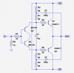
As no gain (voltage) was required, I opted for a text-book diamond structure, with sufficiently fast transistors.
The bias issues bothered me, because for the task at hand emitter resistors would be a nuisance, and the necessity to insert a bias spreader somewhere in the input circuitry wasn't pleasant either.
I then had an intuition: because I need to run the drivers at a very high dissipation (for speed and current drive), the circuit should be thermally stable, without any other explicit measure.
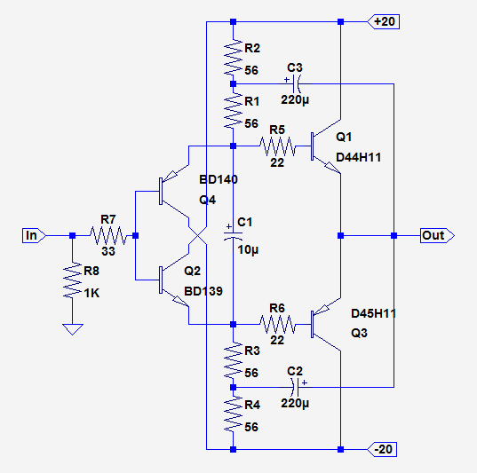
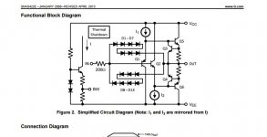
In the schematic below, the drivers run about 60°C higher than the OP devices, but their temperature is referenced to them, because they are bolted to the same heatsink.
As anyone knows, dispensing with emitter resistors is one of the fastest way to get the magic smoke out of an OP stage, (unless other measures are taken, like current drive or bias servo, of course), and I was wary the first time I fired it up (on a limited lab supply, of course).
And guess what? Nothing happened, it simply worked as I hoped it would.
I made some serious stress tests, and everything went smoothly.
I could perform my calibration without problems, but I was intrigued, and still somewhat unbelieving; therefore I built another test buffer, with quite different components, and it seemed to work in the same way.
What are your thoughts about this? The drivers do run much hotter than the OP, but as their junction area is smaller than the OP, this doesn't prevent a quiescent current from circulating, and in principle, a dissipation excursion might lead to thermal runaway, but it looks like my intuition was right: the arrangement remains stable whatever you throw at it (I didn't make a dead output short, because it is not protected, and the issue is predictable, but other than that, I tried pretty much everything)
I recently needed a wide-band buffer to boost the output of a function generator, as I needed to calibrate the equalization of a Rogowski probe.
My usual lab-amps weren't up to the task, because they are essentially beefed-up audio amps.
In particular, I didn't want any global FB loop, as it makes the clean rendering of extreme transients difficult.
As no gain (voltage) was required, I opted for a text-book diamond structure, with sufficiently fast transistors.
The bias issues bothered me, because for the task at hand emitter resistors would be a nuisance, and the necessity to insert a bias spreader somewhere in the input circuitry wasn't pleasant either.
I then had an intuition: because I need to run the drivers at a very high dissipation (for speed and current drive), the circuit should be thermally stable, without any other explicit measure.
In the schematic below, the drivers run about 60°C higher than the OP devices, but their temperature is referenced to them, because they are bolted to the same heatsink.
As anyone knows, dispensing with emitter resistors is one of the fastest way to get the magic smoke out of an OP stage, (unless other measures are taken, like current drive or bias servo, of course), and I was wary the first time I fired it up (on a limited lab supply, of course).
And guess what? Nothing happened, it simply worked as I hoped it would.
I made some serious stress tests, and everything went smoothly.
I could perform my calibration without problems, but I was intrigued, and still somewhat unbelieving; therefore I built another test buffer, with quite different components, and it seemed to work in the same way.
What are your thoughts about this? The drivers do run much hotter than the OP, but as their junction area is smaller than the OP, this doesn't prevent a quiescent current from circulating, and in principle, a dissipation excursion might lead to thermal runaway, but it looks like my intuition was right: the arrangement remains stable whatever you throw at it (I didn't make a dead output short, because it is not protected, and the issue is predictable, but other than that, I tried pretty much everything)
Attachments
Member
Joined 2009
Paid Member
This is very interesting - I'm going to file this away for future use !
Did you find that there is a range of values for the OPT bias string R1, R2, which allows this to work well but outside that range things are awkward ?
Did you find that there is a range of values for the OPT bias string R1, R2, which allows this to work well but outside that range things are awkward ?
Hi Elvee,
Now you know why I like them so much.
Using current sources for R2 and R4 allows you to set the currents and also may allow you to run the drivers at lower temps for low frequency use. The most heat in that circuit will be generated at idle, as in no signal.
This basic circuit makes a dandy headphone amplifier as well. Your DC offset voltage should measure in the mV (~33 mV wouldn't be abnormal). You could probably adjust that with the resistors. I've never had to do that so far. I normally use current sources generated with red LEDs and a BJT transistor. Pretty simple.
-Chris
I did something similar, but with BC546/BC556 for the small transistors, and MJE243/253 for the outputs. Using LED based current sources as suggested by anatech. Makes a great headphone amp.
I found during testing, that the temperature of Q2 and Q4 actually causes bias current to DECREASE the hotter they get. i found that if i blew cold air over them, the bias current in the output stage went up. So it seems as if this design is not prone to thermal runaway in the traditional manner
I found during testing, that the temperature of Q2 and Q4 actually causes bias current to DECREASE the hotter they get. i found that if i blew cold air over them, the bias current in the output stage went up. So it seems as if this design is not prone to thermal runaway in the traditional manner
Very interesting. I am also looking for a preamp or a headphone amp. Simple designs seem to sound fast and natural. I don't have those DH transistors handy. Could 2SC4793 and 2SA1837. Could that work as well? Also for drivers could KSA1831 and KSC3503 be used and would that be even higher bandwidth?
Very interesting. I am also looking for a preamp or a headphone amp.
What are you going to do about the offset?
Hi xrk971,
Yes, those will also work. You should experiment.
Hi ammel68,
What DC offset to speak of? It's normal to run up to even 50 mV, and that isn't harmful to headphones. I've had several uncorrected circuits running an average of 5 ~ 10 mV DC offset as well. Some of this depends on matching the complimentary transistors for beta, although you can never really match a PNP with an NPN. Still, Hfe matching does help with DC offset.
If the fact that there is a little DC offset really bugs you, it's easy to couple the input with a capacitor and provide a DC return resistor. You can also add in a DC servo if you really need no offset to speak of.
-Chris
Hi ammel68,
It's normal to run up to even 50 mV, and that isn't harmful to headphones.
Hi Chris,
Yeah, it may be normal for some, but I don't use anything with 50mv of offset.
Being a buffer with a low input impedance, you'll still need something in front of it with a quite low output impedance.
Most op-amps will be out unless the circuit will work on say 15V rails.
I have some of the DH transistors I use for power supplies, so I may give the circuit a try and see how it sounds.
Replace R1 and R3 with trimpots might let you adjust DC offset and having Hfe matched. Inputs will keep the offset in check below 20mV.
Hi xrk971,
You only need one adjustable control (single turn type), say R4. If R2 was 100R, make R4 a 91R and a 25 or 50 R pot. Couple Q2 and Q4 together on a small heat sink, then Q1 and Q3 on a larger heat sink. If find the drift to be low.
Hi ammel68,
It's so easy to get carried away. Most diamond buffers are very low in DC offset. Use a 5534A to drive these buffers, or a 5532 to drive the pair. The 5534 has higher performance. Of course you can also use the most expensive op amps you can find, but the difference won't be heard in normal listening.
What you are essentially doing here is building a BUF634.
-Chris
Replace R1 and R3 with trimpots might let you adjust DC offset and having Hfe matched.
Possibly, I don't know. I think with some Hfe matching and a low offset circuit in front of the buffer, offset shouldn't be too high.
Chris mentioned improving the circuit with CCSs in place of R2 and R4.
Perhaps he can show what the schematic would look like with those added.
Hi ammel68,
I'm sorry, but I don't have the time for that right now. A little searching for "constant current source" on DIYAudio will show you the different circuits. I find the BJT transistor - LED (red) very good for this. Just replace the resistor with the CCS circuit. You can adjust the offset by using a resistor with a pot in parallel (single turn!).
You're right in that a low-ish impedance source should give you a low DC offset. In the event that your circuit doesn't, just fine adjust the current sources to null out the imbalance.
-Chris
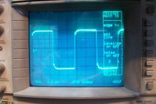
The original circuit had an Iq of 328mA; I decreased the string current by a factor ~5, resulting in an Iq of 136mA.Did you find that there is a range of values for the OPT bias string R1, R2, which allows this to work well but outside that range things are awkward ?
I noticed no particular problem.
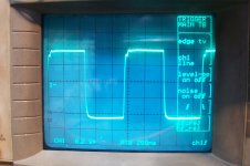
The first pic is a 1MHz squarewave reproduced by the original circuit, and the second by the reduced current version (8 ohm load in both cases).
Hi Elvee,
Now you know why I like them so much.
Using current sources for R2 and R4 allows you to set the currents and also may allow you to run the drivers at lower temps for low frequency use. The most heat in that circuit will be generated at idle, as in no signal.
This basic circuit makes a dandy headphone amplifier as well. Your DC offset voltage should measure in the mV (~33 mV wouldn't be abnormal). You could probably adjust that with the resistors. I've never had to do that so far. I normally use current sources generated with red LEDs and a BJT transistor. Pretty simple.
-Chris
Interesting (and comforting) to see my observations confirmed by othersI did something similar, but with BC546/BC556 for the small transistors, and MJE243/253 for the outputs. Using LED based current sources as suggested by anatech. Makes a great headphone amp.
I found during testing, that the temperature of Q2 and Q4 actually causes bias current to DECREASE the hotter they get. i found that if i blew cold air over them, the bias current in the output stage went up. So it seems as if this design is not prone to thermal runaway in the traditional manner
I think that the scheme should be applicable to many other transistors (although there might be restrictions on peculiar driver/OP combinations).
Very interesting. I am also looking for a preamp or a headphone amp. Simple designs seem to sound fast and natural. I don't have those DH transistors handy. Could 2SC4793 and 2SA1837. Could that work as well? Also for drivers could KSA1831 and KSC3503 be used and would that be even higher bandwidth?
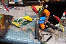
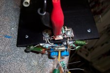
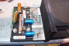
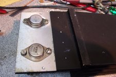
Next pics are the prototype, and an alternative version based on the good ol' 2N3055/MJ2955 pair, running at a somewhat higher current.
It is slower than the previous one, yet its full power bandwidth is in excess of 2.5MHz. Not bad for old and clumsy silicon...
On this one, I have added a 150 ohm after the 4.7 ohm base stoppers, because the Iq was ~700mA (probably due to the larger junction area of the With this fix, it is down to 380mA, more reasonable
3055/2955).
It also appears to be totally thermally stable
Attachments
You could explicitly set the junction temperatures in simulation and find out whether an increase in driver temperature results in an increase or decrease in output stage bias current (in simulation). You could try this for various different choices of device types (.MODELs) from different semiconductor vendors, to reduce the possibility of incorrect conclusions resulting from bad model parameters. For example I find wide variability in the simulation models of BD139 from different semi companies.
I had a preamp that slightly resembled this schematic and I cheated away most of the DC offset by giving the output transistors different heatsinks.
I know exactly how to make a servo ccs for that buffer.. I expect that it can swing rather close to the rails..
I know exactly how to make a servo ccs for that buffer.. I expect that it can swing rather close to the rails..
Either the servo CCS's or just positive servo FB into the diamond itself.
The + FB can be very high Z , just a few microvolts to correct offset ...
especially with almost no emitter degeneration (in this case).
Both you and me have done about a dozen "flavors" of this circuit , eh ?
😀
PS - injecting FB into either the CCS (or heaven forbid the input) , might offend
"purist's" !!
OS
LME49600
http://www.ti.com/lit/ds/symlink/lme49600.pdf
Same concept (below). Either the chip or a DIY equivalent (my pitchfork) can
do 1ppm @ 20Khz into a 20R load.
The "diamond can do" . 🙂
OS
http://www.ti.com/lit/ds/symlink/lme49600.pdf
Same concept (below). Either the chip or a DIY equivalent (my pitchfork) can
do 1ppm @ 20Khz into a 20R load.
The "diamond can do" . 🙂
OS
Attachments
Hi OS,
But building the thing is so much more fun, even if the LME49600 outperforms most of what is built.
Wasn`t that chip discontinued.
-Chris
But building the thing is so much more fun, even if the LME49600 outperforms most of what is built.
Wasn`t that chip discontinued.
-Chris
Hi OS,
But building the thing is so much more fun, even if the LME49600 outperforms most of what is built.
Wasn`t that chip discontinued.
-Chris
Yes , building the LME equivalent with BD xxx's as the class A stage
plus using an OPA xxxx as the feedback/amp was so much more fun.
Still got the 1 ppm with 1/2 discrete's.
Mouser has 300 in stock for 6$ , 6 week factory lead -
does not seem to be discontinued. Many Ebay headphone kits using it.
OS
- Status
- Not open for further replies.
- Home
- Amplifiers
- Solid State
- A diamond paradox?