

Well, it is both, a European Ge alloyed junction transistor in an all glass tube package.
Actually one of my first transistors.
This one has the usual black paint removed.
Without the paint, they made great photo transistors, too.
The official OC70 from Valvo (Philips) and OC602 from Telefunken sold from between 10 to 20 bucks and were either unaffordable or unobtainable.
But from a surplus vendor one could buy unmarked, untested, probably off-spec parts in bags of 10 for a 5er.
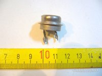
The first picture shows from right to left a match, the unpainted one, a ruler, and the 3 varieties AF, RF, and small power type.
The latter had the transistor in a metal tube inside which made contact with the glass and were supposed to transfer heat to a metal clip through the glass ... I wonder what the thermal resistance would have been ... anyway, 500mA max spec.
I remember that I built a photo-electric guard with those, the small power type driving a relay coil even without a free-wheeling diode.
And the survivors still test good ...


Actually one of my first transistors.
This one has the usual black paint removed.
Without the paint, they made great photo transistors, too.
The official OC70 from Valvo (Philips) and OC602 from Telefunken sold from between 10 to 20 bucks and were either unaffordable or unobtainable.
But from a surplus vendor one could buy unmarked, untested, probably off-spec parts in bags of 10 for a 5er.
The first picture shows from right to left a match, the unpainted one, a ruler, and the 3 varieties AF, RF, and small power type.
The latter had the transistor in a metal tube inside which made contact with the glass and were supposed to transfer heat to a metal clip through the glass ... I wonder what the thermal resistance would have been ... anyway, 500mA max spec.
I remember that I built a photo-electric guard with those, the small power type driving a relay coil even without a free-wheeling diode.
And the survivors still test good ...
Thanks to everybody for sharing!
I feel like a kid again.
Those devices were too light. That is the reason for the Wrench to hold the wires down, Right?
And the one device on the right side of the ruler is a Matched device (the Match is next to it).
I feel like a kid again.
Those devices were too light. That is the reason for the Wrench to hold the wires down, Right?
And the one device on the right side of the ruler is a Matched device (the Match is next to it).
Looks like two of the leads are twisted together. Was that an accident or was somebody actually worried about ESD? 😀
But why was the choice of a hermetically sealed glass tube for a transistor a wise decision at that time ?
Well, Ge as opposed to Si does not grow a stable, gas- and moisture tight oxide.
In other words, it corrodes fast in the presence of O2 and H2O.
When Philips/Valvo introduced the metal package they got it all wrong.
The metal can was tin plated on the inside and filled with silicone grease which does a pretty good job of holding back gas and water.
But it turned out that the combination supported the formaton of tin whiskers on the inside.
Over time - often less than a year in service - these filaments grew long enough to form an inner connection between the can and one of the electrodess. And in case of IF and RF transistors like AF116 and others, that had a 4th lead to connect the metal can with circuit ground, this was detrimental. AF116 in TO-7 was finally replaced by AF126 in a much smaller TO-72 which did not have this problem.
Interestingly enough the problem of tin whiskers re-appeared many decades later when the industry turned to lead-free solder. This time it happened on tightly packed PCBs.
Last edited:
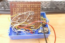
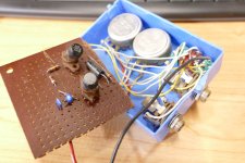
The germanium Fuzz Tone box that refused to die.
The first iteration of this build happened sometime about 1967 or 68. A friend had received a VOX Tone Bender guitar pedal for a birthday gift. Within a day or two we opened it up and traced its rather simple two transistor schematic. I cloned the circuitry on some quality phenolic proto board using sockets for the transistors. A couple of old Japanese transistor radios offered up some fresh germanium for the active devices. The other parts were salvaged from whatever I had to make a working pedal. All was stuffed into a plastic box which did not live long under my foot. The plastic box cracked, and the plastic bat handles on the switches broke off.
There were several other iterations before the final design of which there were three made in the early 70's. All were in heavy plastic boxes that sat on or near the guitar amp with controls in easy reach with a single long cable to a footswitch mounted in a wood housing. It actuated a relay for "true bypass" switching.
The proto board from the first iteration wound up in another cheap plastic box which was unsuitable for serious guitar use. It however was used to screen out "good germanium" for fuzz tone boxes. I found that version when I was moving out of Florida in 2014. It now has a pair of Sony transistors of unknown origin, and it still works.
The Vox Tone Bender / Dallas Arbiter Fuzz Face circuit does not sound good with silicon devices.
Attachments
When I was about 10 I asked my dad to buy me a transistor for a 1-transistor radio project. It was a Russian P213B, the only available type that time. It was super expensive. The leads were isolated and fixed in the metal case by glass. I mounted all components in a nice wooden box, with spider web cabling. I bent and turned the leads of the transistor so much that the glass isolation eventually broke an one lead came out. No problem, I pushed it back and by trial and error found a position where it actually worked! A quick fix with a drop of glue, and it was like new.
Attachments
Nope, otherwise they wouldn't use it to make infra-red lenses. To quote from a manufacturer of Ge optics:Well, Ge as opposed to Si does not grow a stable, gas- and moisture tight oxide.
In other words, it corrodes fast in the presence of O2 and H2O.
At room temperature it is basically stable against corrosion in the normal sense of the word. I suspect the transistor is sealed to avoid unwanted diffusion of dopants into the chip, since as a semiconductor trace impurities in parts-per-trillion really matter, not an issue for lenses.optical lenses made of polished germanium. These lenses are rugged and resistant to corrosion, and are ideal for harsh environments and applications where there is constant exposure to the elements.
BTW my phone has a thermal camera built in with a Ge lens, its been in and out of my bags/pockets etc for 6 years and not a hint of any corrosion.
Is it possible that glass was the cheapest technology at the time? Only issue is it limits power dissipation and is light sensitive. The fact that so many are still alive is a testament to the choice of glass.
Well they made glass diodes, like the 1N34 and 1N60, right? So it would be a likely first step in transistor evolution.
Probably less likely for dendrite growth than in metal cans, too. Not uncommon for a totally unused Ge transistor to test short circuit.
Probably less likely for dendrite growth than in metal cans, too. Not uncommon for a totally unused Ge transistor to test short circuit.
I remember playing with an OA81 glass diode with the black paint scratched off.
I got it to light-up like a globe for a good 3 seconds - then disconnected it.
Measuring after it still functioned as a diode. I was amazed that the 'whisker' & junction could do this
and still survive! I guess I caught a 'pre-glimpse' of future LED's. (although not exactly the same thing)
I got it to light-up like a globe for a good 3 seconds - then disconnected it.
Measuring after it still functioned as a diode. I was amazed that the 'whisker' & junction could do this
and still survive! I guess I caught a 'pre-glimpse' of future LED's. (although not exactly the same thing)
My friend's crystal set used a bakelite 1N34.
There were no 1N34 and 1N34A glass diodes in town.
A local TV radio shop had a 1N60, but they did not know if it would work in my crystal set. How I wished I had risked spending my money on a 1N60.
Old too Soon, and Smart too Late.
There were no 1N34 and 1N34A glass diodes in town.
A local TV radio shop had a 1N60, but they did not know if it would work in my crystal set. How I wished I had risked spending my money on a 1N60.
Old too Soon, and Smart too Late.
https://www.google.com/imgres?imgur...UKEwiM7InQkLOAAxV0m2MGHcT0DgcQMygAegUIARDxAQI was also fascinated by Light Activated Silicon Controlled Rectifiers and their amazingly high operating voltage.
Well they made glass diodes, like the 1N34 and 1N60, right? So it would be a likely first step in transistor evolution.
Probably less likely for dendrite growth than in metal cans, too. Not uncommon for a totally unused Ge transistor to test short circuit.
It was the tin from the metal cans growing whiskers. https://nepp.nasa.gov/whisker/anecdote/af114-transistor/index.html
If you used a transistor tester that wasn't designed to recognize germanium transistors,Not uncommon for a totally unused Ge transistor to test short circuit.
the .3 volt junction drop of germanium could certainly show-up as faulty.
Silicon has a .6 volt junction drop.
- Home
- Amplifiers
- Tubes / Valves
- A device that does many things a vacuum tube does