I've been doing some updating on my existing circuits and thought it might be fun to submit them here for comments...
The first thumbnail is an RIAA pre-amp.
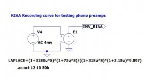
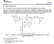
The second is the recording side RIAA curve used for testing in LTSpice.
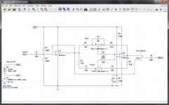
The third is a pretty standard tone control design.
The first thumbnail is an RIAA pre-amp.
The second is the recording side RIAA curve used for testing in LTSpice.
The third is a pretty standard tone control design.
Attachments
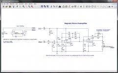
RIAA:
Why the 1k extra Johnson noise on the input? That's going to really affect an MC source.
Why 1.5nF load capacitance when typical MM cartridges want a few 100pF only? Is it meant to be switchable?
Why use a 5532 for MC when its noise-optimized for a few k ohms source? Its best to have a separate head-end for MC due to the very low impedance - its hard to optimize one amp for two very different source impedances.
Tone:
The Baxandall circuit is inverting, why not use the 2nd opamp to re-invert the signal, so that both are operating with zero common-mode distortion, and the phase is correct on the output?
Its recommended to keep bipolar bias currents out of potentiometers to reduce noise when turning the pot - if the track is at all scratchy it interrupts the bias to the opamp and causes large output voltage swings. AC coupling the pot will reduce scratchiness to the amplitude of the signal itself, not the supply rails.
JFET or CMOS opamps have so little input current that the input capacitance smoothes the scratchiness away without special measures.
Hope this gives you some pointers for some of the less commonly understood points of design for these circuits(!) I recommend the works of Douglas Self for learning many of these subtler points, esp. "Small Signal Audio Design" and "Electronics for Vinyl"
Last edited:
Hello Mark ...
Thank you, comments noted and under consideration.
As I said these are older circuits that worked with older op-amps but there's always room for improvement.
Thank you, comments noted and under consideration.
As I said these are older circuits that worked with older op-amps but there's always room for improvement.
BTW the LTSpice directive is hard to copy/paste from an image.
Ahh, yes, I imagine it would be. Sorry.
The ASC file for it is attached...
This generates a recording side curve, which is what is on the Vinyl.
To use it, include it into your schematic, connect it to your input and tune the pre-amp output to be flat.
Attachments
Last edited:
This phono stage has a number of issues.
If you want to power it by anything that isn't a battery, input biasing should be changed from a simple resistor divider (R1/R2) to something more elaborate, like R/RC-R (maybe 47k/(47k||2µ2) - 47k). MM phono cartridge impedance ends up in the double-digit kOhms towards the upper end of the audible range, resulting in poor PSRR.
Note that some NE5532s are only specified from +/-5 V up.
1n5 of input capacitance is unacceptably high for the majority of MM phono cartridges, even more so when in parallel to 100k. Ideally, you want some choice there - sockets may be easiest to do (47p - 100p - 220p - 330p - 470p - 680p should cover most cases). Also stick with 47 kOhm unless you have very good reasons. If RF ingress becomes a problem, employ inductive input filtering.
As mentioned, noise performance is totally inadequate for MC use - input noise is about 20 dB higher than what you want in a good MC amp. It's not spectacular but OK for MM.
For MC use I would suggest adding a dedicated prepre fed by an extra set of inputs. Here's a fancy one that is arguably crying for paralleled transistors or some types with lower Rbb' (MPS8599 may be worth a shot). Satisfactory performance is, however, also achievable with just 2-3 discrete transistors.
Attachments
This phono stage has a number of issues.
Thank you for commenting. I will consider your input during the next prototyping session.
If you want to power it by anything that isn't a battery, input biasing should be changed from a simple resistor divider (R1/R2) to something more elaborate, like R/RC-R (maybe 47k/(47k||2µ2) - 47k). MM phono cartridge impedance ends up in the double-digit kOhms towards the upper end of the audible range, resulting in poor PSRR.
Note that some NE5532s are only specified from +/-5 V up.
Ahh, the 9vdc spec on the schematic was a test. I was varying the voltage to see what differences I should expect. In the final design, the pre-amp will most likely be run on 24vdc, along with the tone circuit.
1n5 of input capacitance is unacceptably high for the majority of MM phono cartridges, even more so when in parallel to 100k. Ideally, you want some choice there - sockets may be easiest to do (47p - 100p - 220p - 330p - 470p - 680p should cover most cases). Also stick with 47 kOhm unless you have very good reasons. If RF ingress becomes a problem, employ inductive input filtering.
I'm actually thinking about dropping the MC support. It would make life a lot simpler.
Ahh, yes, I imagine it would be. Sorry.
The ASC file for it is attached...
This generates a recording side curve, which is what is on the Vinyl.
To use it, include it into your schematic, connect it to your input and tune the pre-amp output to be flat.
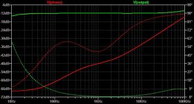
Ah, that's useful, haven't played with LAPLACE before. Used it with one of my RIAA circuits, got this nice set of response graphs:

"emf" in magenta is the output of the inverse RIAA, "preamp_input" in red is with the resistance/inductance and preamp input load applied to this showing the modest peaking and ultrasonic roll-off. green "output" is after my RIAA amp circuit, and then blue "rumble" is after the subsequent 4 pole subsonic filter.
( I modelled 400 ohms and 500mH for the cartridge into 47k || 200pF - it shows the cartridge reactance is quite a factor in the accuracy of the response, being about 1dB of peaking )
Last edited:
Thanks for sharing the Laplace directive usage too.
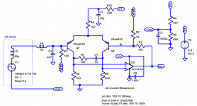
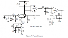
I can share one MC gain stage that I was playing with a long time ago, it was featured in a AudioExpress mag article a few years ago.
iirc it used mpsa12 and its complement mpsa62 for the o/p, I sub'd those because I did not have or know how to make a model for them.
I can share one MC gain stage that I was playing with a long time ago, it was featured in a AudioExpress mag article a few years ago.
iirc it used mpsa12 and its complement mpsa62 for the o/p, I sub'd those because I did not have or know how to make a model for them.
Attachments
Last edited:
Ah, that's useful, haven't played with LAPLACE before. Used it with one of my RIAA circuits, got this nice set of response graphs:
It drove me nuts getting that equation right (which might explain quite a lot, actually 😉 )
Here are the results from my circuit in the first post. Gotta love that nice straight green output line. It tells me that the recording and playback curves are near perfectly complimentary.
Attachments
Thanks for sharing the Laplace directive usage too.
You're welcome. I'm always happy to share the (non secret) stuff.
It drove me nuts getting that equation right (which might explain quite a lot, actually 😉 )
Here are the results from my circuit in the first post. Gotta love that nice straight green output line. It tells me that the recording and playback curves are near perfectly complimentary.
My RIAA simulation is based on this approach, which separates out all the zeroes and poles into separate RC sections, so in theory its a perfect match to the inverse transform (ignoring opamp non-idealities and compensation components):

Followed by a four-pole Butterworth rumble filter using Sallen Key stages.
My RIAA simulation is based on this approach, which separates out all the zeroes and poles into separate RC sections, so in theory its a perfect match to the inverse transform (ignoring opamp non-idealities and compensation components):
Followed by a four-pole Butterworth rumble filter using Sallen Key stages.
Nice! I've seen similar configurations, including all passive versions using FETs for gain. It's one of the most designed circuits I know of.
Me, I'm old school. The design I posted started out with a ua741 way back in 1980 or so. I realize it needs some touches, which is why I asked for comments, but it was a working circuit at one time.
To be honest, I've been thinking about buying a turntable with the pre-amp built in. There are advantages to keeping the gain close to the transducer.
My personal thing is doing the most with the least. When studying electronics in school our teacher always hammered at us... "First you get it to work at all, then you get it to work right, and finally you take out everything that isn't needed to make it work." ... Guy hasn't been wrong yet. LOL.
It did look like something that started life with a 4558 or similar...Me, I'm old school. The design I posted started out with a ua741 way back in 1980 or so. I realize it needs some touches, which is why I asked for comments, but it was a working circuit at one time.
µA741, eh? Had to look for a bit until I found some clues to the noise level of that one. The dual version MC1458 as made by Philips was given with 30 nV/√(Hz). Better than an LM358, but still quite a bit worse than a 4558.
If it's any consolation, P06 is considerably noisier for what I suspect is a similar kind of history. (The entire feedback network of the first stage is about an order of magnitude too high in impedance.)
Your design is about on par with an average 4558-based typical integrated amp circuit of the 1980s in terms of noise and no doubt better in distortion.
Certainly, especially when you are a fan of Audio Technica MM cartridges. Not a few of those want 47 kOhm || 100-200 pF, cable included (100-150 pF, typ).To be honest, I've been thinking about buying a turntable with the pre-amp built in. There are advantages to keeping the gain close to the transducer.
Integrated phonopres weren't usually very fancy though, at least back in the '70s.
Basically it isn't wrong - but you have to figure in decades worth of experience, refinement and competition. When "good enough" is good enough, don't be surprised if you get steamrolled. You only need to look at how the Japanese turned several industries upside down.My personal thing is doing the most with the least. When studying electronics in school our teacher always hammered at us... "First you get it to work at all, then you get it to work right, and finally you take out everything that isn't needed to make it work." ... Guy hasn't been wrong yet. LOL.
Nowadays there are helpful websites, helpful forums such as the Analogue Source department next door, and you can access schematics for numerous commercial devices easily (*cough* HiFiEngine *cough*). Phono preamps have been a solved problem for 3 decades.
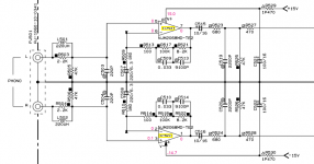
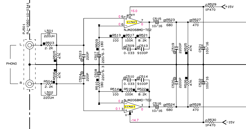
If you fancy a single-chip design, this is what has been gracing Yamaha's more down to earth integrated amps for years:
This is likely to be as low noise as they typically come for MM, short of going for a low-noise FET input stage. (This opamp seems to be at least on par with an NE5534A in the voltage noise department, and possibly current noise as well given the moderate input bias current spec.) Knowing the NJM2068's somewhat limited output driving abilities (less robust than the NE5532's), I would imagine that distortion performance could be improved by including a discrete Class A buffer stage in the loop, headphone amp style. With 280 ohms worst-case, it doesn't have to be super-duper powerful, a pair of BC639/640 (or 2N5551/5401) at ~5 mA or so seems easily sufficient. (You can go AB with some high-beta transistors if you insist, maybe BC550/560 or KSC1845/KSA992.) One might even consider going single-ended for simplicity's sake. I could draw up a schematic later if you're interested.
Attachments
Last edited:
It did look like something that started life with a 4558 or similar...
µA741, eh? Had to look for a bit until I found some clues to the noise level of that one. The dual version MC1458 as made by Philips was given with 30 nV/√(Hz). Better than an LM358, but still quite a bit worse than a 4558.
If it's any consolation, P06 is considerably noisier for what I suspect is a similar kind of history. (The entire feedback network of the first stage is about an order of magnitude too high in impedance.)
Your design is about on par with an average 4558-based typical integrated amp circuit of the 1980s in terms of noise and no doubt better in distortion.
Certainly, especially when you are a fan of Audio Technica MM cartridges. Not a few of those want 47 kOhm || 100-200 pF, cable included (100-150 pF, typ).
Integrated phonopres weren't usually very fancy though, at least back in the '70s.
Basically it isn't wrong - but you have to figure in decades worth of experience, refinement and competition. When "good enough" is good enough, don't be surprised if you get steamrolled. You only need to look at how the Japanese turned several industries upside down.
Nowadays there are helpful websites, helpful forums such as the Analogue Source department next door, and you can access schematics for numerous commercial devices easily (*cough* HiFiEngine *cough*). Phono preamps have been a solved problem for 3 decades.
If you fancy a single-chip design, this is what has been gracing Yamaha's more down to earth integrated amps for years:
This is likely to be as low noise as they typically come for MM, short of going for a low-noise FET input stage. (This opamp seems to be at least on par with an NE5534A in the voltage noise department, and possibly current noise as well given the moderate input bias current spec.) Knowing the NJM2068's somewhat limited output driving abilities (less robust than the NE5532's), I would imagine that distortion performance could be improved by including a discrete Class A buffer stage in the loop, headphone amp style. With 280 ohms worst-case, it doesn't have to be super-duper powerful, a pair of BC639/640 (or 2N5551/5401) at ~5 mA or so seems easily sufficient. (You can go AB with some high-beta transistors if you insist, maybe BC550/560 or KSC1845/KSA992.) One might even consider going single-ended for simplicity's sake. I could draw up a schematic later if you're interested.
Ummm ... Okay.
Many possibilities, I posted this jfet composite in another thread, it is from the LSK489 application note. I did discover that I think the 75uS comps are incorrect, C4 should be 22n. If you find lsk489 too expensive you could sub low cost jfets. A DC servo could be used to eliminate C5 and o/p ac coupling cap.
Even the new TI OPA1656 can be used. I called it the new NE5532
Even the new TI OPA1656 can be used. I called it the new NE5532
Attachments
Last edited:
- Home
- Source & Line
- Analog Line Level
- A couple of quick circuits