I hope somebody can help me identifying this line stage circuit. I don’t think it’s an anode (or plate) follower, and it is not a common cathode amplifier. What I don’t really understand is the complete lack of a shunting from the cathode to the ground. The common cathode circuit has a resistor with the bypass cap, but here we have the cathode directly connected to the ground... can't find this circuit on books.
Can somebody help me in understanding how it works?

Can somebody help me in understanding how it works?
Not so unusual circuit.
It's the simplest grounded cathode gain circuit, not using cathode bias and degeneration.
Negative grid bias is provided by the voltage drop across the high value (probably several MOhms) R1 due to the grid leak current.
It's the simplest grounded cathode gain circuit, not using cathode bias and degeneration.
Negative grid bias is provided by the voltage drop across the high value (probably several MOhms) R1 due to the grid leak current.

currently it's an ECC88, but I'd like to try with 6SN7.
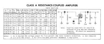
So this is called "Resistor Coupled Amplifer" ?
So this is called "Resistor Coupled Amplifer" ?
Grid leak bias, which is a variant of fixed bias.
It will be in Radiotron Designer's Handbook, 4th Edition.
http://www.tubebooks.org/books/rdh4.pdf.
It will be in Radiotron Designer's Handbook, 4th Edition.
http://www.tubebooks.org/books/rdh4.pdf.
These values and proper operation of grid leak bias were derived for new tubes over 70 years ago. An old tube as well as some new production tubes may have a weaker vacuum than a new tube did 70 years ago. The ions present in these tubes can bleed off the negative charge that accumulates on the grid making grid leak bias unstable or even impossible. Any overload on the input can also drive the grid highly negative causing cutoff until the blocking cap discharges. A 12 year old kid (me) with a Fender Champ clone made from scrap radio and TV parts did not understand why my DIY fuzz pedal could kill the guitar amp for 10+ seconds. A change to cathode bias and swapping that 2 meg grid leak for a 47K fixed everything. The chart shows a 10 Meg grid leak resistor for a 6SN7. It wouldn't take much of an overload to upset the bias enough to cutoff a tube.
I would use a cathode resistor in the 2 to 6K range for a 6SN7 and choose the rest of the parts according to your B+ voltage from the chart on page 3 in the datasheet.
I would use a cathode resistor in the 2 to 6K range for a 6SN7 and choose the rest of the parts according to your B+ voltage from the chart on page 3 in the datasheet.
Attachments
Thanks to all. Did I get it correctly that the actual biasing will depends on the specific tube unit plugged in? And that, ceteris paribus, for a given B+ and grid leak resistor there may be a range of tube type that could work although this is not predictable?
The reason why I asked this is because I love the Counterpoint tube preamps' sound , both the SA 3.1 and the SA 5.1. This is the type of gain stage in those preamps. That's interesting. I wonder whether the sound the Counterpoint's sound signature can be somewhat connected to this unusual kind of circuit.
The reason why I asked this is because I love the Counterpoint tube preamps' sound , both the SA 3.1 and the SA 5.1. This is the type of gain stage in those preamps. That's interesting. I wonder whether the sound the Counterpoint's sound signature can be somewhat connected to this unusual kind of circuit.
Sometimes illogical choices make beautiful music.
If it sounds good, it is good.
Still this kind of bias is unpredictable, depends on tube and shifts as tube ages.
If it sounds good, it is good.
Still this kind of bias is unpredictable, depends on tube and shifts as tube ages.
Perhaps this explains why with some tube my preamp sounds magic and with others it doens't stand out.
Let me ask another question. I read the documentation you guys pointed out + some other reference spotted online. Did I understood correctly that the input cap (C1 in my schematic above) is very important and cannot be removed?
In many line stages, one assumes that DC has been filtered out in the previous stage and one can skip the input cap.
The input coupling cap is essential with this circuit to not load down the bias voltage by any resistance before the cap.
You need the input coupling capacitor for a circuit with grid leak bias, for the same reason you need a capacitor with fixed bias output tubes in a power amplifier.

That's fixed bias, not grid leak bias. Higher gain and distortion, and higher variability with the individual tube than cathode bias.
During the 2nd half of the 19303s many radio receivers had all cathodes tied to the chassis.
Chassis was common in the circuit. That saved time on the production line.
Bias was by the voltage developed in the loudspeaker electromagnet coil in the -ve lead of the B+ supply.
The largest of the voltages was used as grid bias on the output tube, usually a pentode.
And taps on a resister for the RF, IF amplifiers & converter.
Bias depended on signal level as the AGC did its work.
The whole thing was quite an improvement over previous designs.
And most importantly it brought the World of information to many people.
Who may not otherwise afford it. 👍 👍
Ah okay thanks 🙂 I did not know that! Just thought I’d throw it out here to see if it was like a red flag to anyone.. those tubes are not easy or cheap to come by! The STR is certainly more rock and roll than a regular twin 😉 it’s widely misunderstood but I find quite nice to play. Very flexible, and the master volume functions better than.. any other amp I have 😉
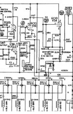
The triode V3C gets its negative grid bias thru what looks like a
LV negative supply via a 10K resister & an Electrolytic Bypass Cap.
LV negative supply via a 10K resister & an Electrolytic Bypass Cap.
- Home
- Amplifiers
- Tubes / Valves
- A circuit without a cathode resistor?