Very helpful! Appreciate it. So you think that they were likely going for more compression when you lay into it?
Ah I see.. it comes from the -dc voltage from the output tube bias.. and is knocked down to (it says) -2.4vdc..
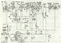
For the sake of completeness & to satisfy the curious & lurkers,During the 2nd half of the 19303s many radio receivers had all cathodes tied to the chassis.
here is a typical receiver from the late 1930s. Octal tubes but still
has grid caps so I'm thinking 1937, 1938.
All the tube cathodes are tied to common. In this example the bias is developed across
resisters 13 & 23 on the schematic lower RHS,, in the return lead to the to the CT of the PT.
Bias for the front end converter & IF amp is by the receiver AGC (Automatic Gain Control}.
The 6A7G & 6K7G are variable mu & have a long grid base in order to handle
a large variation in signal strength.
Hope some or all of this makes sense. 🙂
Attachments

Anyone curious about grid leak bias might like to read "Distortion in Voltage Amplifiers" Feb 1953, p28.
https://www.worldradiohistory.com/Archive-All-Audio/Archive-Audio/50s/Audio-1953-Feb.pdf
(Check out the section 'horrible example')
https://www.worldradiohistory.com/Archive-All-Audio/Archive-Audio/50s/Audio-1953-Feb.pdf
(Check out the section 'horrible example')
The distortion curves of Fig. 11 seem to be interchanged.Anyone curious about grid leak bias might like to read "Distortion in Voltage Amplifiers" Feb 1953, p28.
https://www.worldradiohistory.com/Archive-All-Audio/Archive-Audio/50s/Audio-1953-Feb.pdf
(Check out the section 'horrible example')
Back in 1970s I used 6J32P pentode for input stage of a guitar amp with 4M7 resistor. It sounded lovely!