200cm is quite some depth 😱 200mm or 20cm 🙂
If it wasn't interesting I wouldn't have offered. It has taken time but I don't consider it wasted.
I'll try some basic things first to try and confirm what is going on then look at something more Rockport like.
Sure. Thank a lot fluid 🙂
This time I added an extra zero by mistake. What I meant was 20cm.. 😀😀
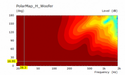
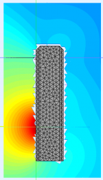
I have run another simulation with a slightly different approach and while there are some differences the overriding peak dip has not been altered significantly. the frequency is slightly different this time at 388Hz.
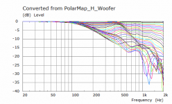
In this sim I have used some dimensions from Vineeth to represent the cone and surround of the Satori WO more accurately and an Le Script which doesn't have any effect in the graphs below which are normalized directivity.
Smoothing the edges on the front and back around the woofer does have some beneficial effect on the overall smoothness of the response which is no surprise, the baffle is 300mm in this case to account for the roundovers and 250 deep from front to back.
Edge diffraction is not having any significant role. Changes in vertical position to come.
Attachments
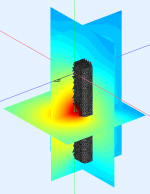
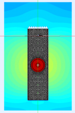
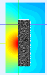
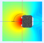
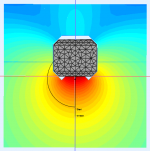
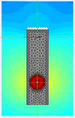
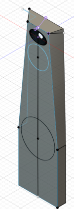
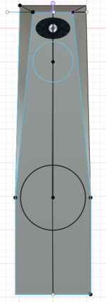
Here is the next iteration. This time the woofer has been moved down 200mm from the other simulations and there is a 36mm chamfer on the front baffle and rear of the enclosure. This is much easier to model at a lower resolution and has no appreciable effect on the result.
I think this is an improvement and the polar curves show the off axis peaking hasn't gone but it is less severe.
There is also an interesting effect at a higher frequency 725Hz where the diffraction from the chamfered edge is contrasted against the diffraction from the top flat edge.

I think this is an improvement and the polar curves show the off axis peaking hasn't gone but it is less severe.
There is also an interesting effect at a higher frequency 725Hz where the diffraction from the chamfered edge is contrasted against the diffraction from the top flat edge.
Attachments
-
 725Hz Edge diffraction.png100.3 KB · Views: 655
 -
 Lower woofer TD.png38.5 KB · Views: 117
 -
 Lower woofer side.png90 KB · Views: 119
 -
 Lower woofer front.png91.2 KB · Views: 124
 -
 Lower woofer Diag.png88.6 KB · Views: 126
 -
 Lower woofer H Polar Curves.png19.1 KB · Views: 134
 -
 Lower woofer H Polar.png17.9 KB · Views: 113
Thanks fluid.. 🙂
These are some very encouraging results.. especially the last one.. 😀
So chamfers all around are good. But I couldn't differentiate much between the attenuation of the wave at the chamfered edge vs straight edge at the top and side. Could you please explain a little bit more about it.. ?
These are some very encouraging results.. especially the last one.. 😀
So chamfers all around are good. But I couldn't differentiate much between the attenuation of the wave at the chamfered edge vs straight edge at the top and side. Could you please explain a little bit more about it.. ?
In the main picture above you can see a more jagged edge to the colours on the top cabinet edge that has no chamfer if you look closely, the shape of the pattern is slightly less even. It is not much but it is there, all these little things can add up in a design.
In the main picture above you can see a more jagged edge to the colours on the top cabinet edge that has no chamfer if you look closely, the shape of the pattern is slightly less even. It is not much but it is there, all these little things can add up in a design.
Thanks for pointing out these differences.. now I see it 🙂
Now that the woofer is closer to the floor like the Rockport design, I think there will be additional floor boundary reinforcement to the lower frequencies which may also be good to the overall design I think..
Yes there will be. Their speakers might be wildly expensive but there is some good design in there too, which is not always the case when the price is that high.Now that the woofer is closer to the floor like the Rockport design, I think there will be additional floor boundary reinforcement to the lower frequencies which may also be good to the overall design I think..
Yes there will be. Their speakers might be wildly expensive but there is some good design in there too, which is not always the case when the price is that high.
ok.. 🙂
Looking at the effects of all the chamfers, now I am feeling like with big rounded chamfers to the back/tapering down the width of the cabinet to the back compared to the front (such that the the width at the back of the box reaches about half the width at the front/baffle), we might be able to control the low frequency diffraction effects better.. My line of thought being a "chamfer" means differently to waves at higher and lower frequencies. For low frequencies to see it, seems like its size will definitely matter. Like in the attached pic, in which I tried to draw something similar... 🙂 (inspired again by revel M16 and Rockport cabinets)
(I haven't applied the top side chamfers in pic, for which you had done simulations above. But I will definitely add it in a final design of the cabinet based on all these studies 🙂 )
Attachments
Last edited:
It would be nice to compare just chamfers vs roundover. Maybe around 32mm since that is about as a big a router bit that can be safely used on a handheld router, or at least that I feel safe using. And maybe model both the woofer and tweeter.
Fluid did a simulation for me some time ago which compared a 37 mm roundover edge to a 37 mm chamfer of 45 degrees... the differences were insignificant.
This is something else to try, wesayso's cabinet linked before is a very good way of doing it as there is no defined edge. Seeing the difference will be interesting but there is much more CAD modelling in something like that.ok.. 🙂
Looking at the effects of all the chamfers, now I am feeling like with big rounded chamfers to the back/tapering down the width of the cabinet to the back compared to the front (such that the the width at the back of the box reaches about half the width at the front/baffle), we might be able to control the low frequency diffraction effects better.
As Jim says above there is very little difference, it mainly comes down to the dimension. If a bigger chamfer is easier to make then it will be better than a smaller roundover. A rounded chamfer is kimmo's favourite. The angle and how that affects the effective width of the baffle have a part to play too.It would be nice to compare just chamfers vs roundover. Maybe around 32mm since that is about as a big a router bit that can be safely used on a handheld router, or at least that I feel safe using. And maybe model both the woofer and tweeter.
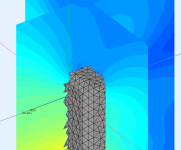
You can see above in the mesh between the roundover and the chamfer that the chamfer models really well with larger triangles and nice aligned vertices. The roundover takes much more mesh resolution to model correctly and bogs everything down.
The differences in edge treatment have much more effect at higher frequencies but you can see in these simulations above that every dimension plays a part to some extent.
I still hope to get your waveguide working in a finite baffled simulation


I have got the augerpro waveguide to simulate properly in a finite baffle. The results are quite encouraging.
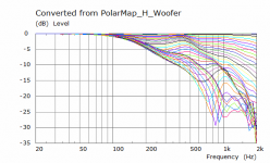
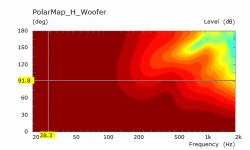
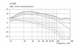
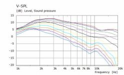
Horizontal and Vertical SPL between 0 to 90 10 degrees apart.
Hi fluid,
Thanks for this simulation.. 🙂
Can you help me understand what all are the things that we should look for in a frequency response graph of a waveguided tweeter, in general?
How do we identify the good trends in the above graph?
Thanks
What I look for in those graphs is first the highest SPL which is usually where the greatest gain from the waveguide is before it tails off and the driver is not getting much if any help.
How even and similar to each other the lines are gives an indication as to the smoothness of the off axis and how well any EQ will apply over a wide range.
The difference in slope between the on axis and far off axis will show in the DI.
I would prefer the lines not cross over each other, that will indicate ripples or peaks in the off axis. They come close together here but not cross. To do better is not easy.
Having the zero 10 and 20 degree curves be very similar will bode well for any listening window measurements that are made.
There are two things that you can see in these graphs that are somewhat inherent to dome tweeters on waveguides. The on and near axis depression at 12K and the deepening off axis through at 15 to 18K. These depend on the shape of the dome and surround. Even the T25B Bliesma with the inverted surround still has them. A flatter dome or a smaller one helps but then it loses something else.
The elliptical shape and smaller vertical dimension causes the vertical directivity to be lost earlier and changes the frequency and shape of the dome issues.
An axisymmetric waveguide will not have that issue but then it will need a slightly different profile to avoid on and near axis ripples.
All in all there is not much better to be be done with a dome in a waveguide.
What I look for in those graphs is first the highest SPL which is usually where the greatest gain from the waveguide is before it tails off and the driver is not getting much if any help.
How even and similar to each other the lines are gives an indication as to the smoothness of the off axis and how well any EQ will apply over a wide range.
The difference in slope between the on axis and far off axis will show in the DI.
I would prefer the lines not cross over each other, that will indicate ripples or peaks in the off axis. They come close together here but not cross. To do better is not easy.
Having the zero 10 and 20 degree curves be very similar will bode well for any listening window measurements that are made.
There are two things that you can see in these graphs that are somewhat inherent to dome tweeters on waveguides. The on and near axis depression at 12K and the deepening off axis through at 15 to 18K. These depend on the shape of the dome and surround. Even the T25B Bliesma with the inverted surround still has them. A flatter dome or a smaller one helps but then it loses something else.
The elliptical shape and smaller vertical dimension causes the vertical directivity to be lost earlier and changes the frequency and shape of the dome issues.
An axisymmetric waveguide will not have that issue but then it will need a slightly different profile to avoid on and near axis ripples.
All in all there is not much better to be be done with a dome in a waveguide.
Thanks again fluid.. 🙂
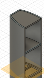
A somewhat Rockport Atria like layout but without the tilted baffle. Maybe keeping the vertical chamfer the same angle would look better?
Attachments
Last edited:
A somewhat Rockport Atria like layout but without the tilted baffle. Maybe keeping the vertical chamfer the same angle would look better?
Thanks a lot fluid. 🙂
This baffle shape already looks really good to my eyes. 😀😀
Regarding tilted baffle, I didn't plan to include it initially thinking that my tweeter-mid might already be closer in terms of acoustic centers due to the waveguide. Also since I have DSP, I thought time alignment wouldn't matter much?
Regarding vertical chamfers, I didn't understand completely. Are you referring to the keeping the same angle as the original design of Rockport Atria? I find the original chamfer design on the Atria very good in terms of looks.
I didn't think seriously about the functionality part till now. So far, I just followed Heismann acoustics's recommendation of keeping the minimal baffle around the tweeter and using roughly 30 to 35 degree chamfers. However I have seen Kimmosto saying something like 45 degree chamfers in some post. So I am a little confused about from a functionally point of view, what would be a good chamfer now.
Last edited:
Hi,
A multi (different) angled one.
The point being that it isn't right angle and an approximation of a rounding overall. The 'softer' the angle(s) the better.
But don't agonize over this: a chamfer is better that bare none. The closer you are to a roundover the better theorically, in practice it isn't 'this' important except if you want to satisfy your brain. 🙂
You are right about dsp and angling of front baffle: once you can compensate using delay it isn't needed anymore ( what Dunlavy pointed in the interview about 'the Magnus' versus the SC-VI where he offseted each box- an extreme case of face tilting).
Last edited:
It doesn't. It was mentioned as there is often someone who will cheerfully point out that it can't be like the Rockport because that baffle is tilted 😉Also since I have DSP, I thought time alignment wouldn't matter much?
Yes the original has the same or similar angle between the top and side chamfers. I agree that it looks good in the original. I tried half that at 22.5 for the top and 45 for the sides.Are you referring to the keeping the same angle as the original design of Rockport Atria? I find the original chamfer design on the Atria very good in terms of looks.
I'm not too sure if there can be a simple answer as any faceted baffle has more at play than just the angle. The sharper the angle the less apparent width to the baffle will appear in the response, but the extended transition can help reduce the edge diffraction. With the higher vertical directivity of the elliptical waveguide at the highest frequencies, it will behave differently to the round waveguide in the Rockport. I don't know exactly what difference it will make, I will try both as it it will create another data point.So I am a little confused about from a functionally point of view, what would be a good chamfer now.
I'm not sure about the first but I agree with the second 🙂Hi,
The closer you are to a roundover the better theorically, in practice it isn't 'this' important except if you want to satisfy your brain. 🙂
It doesn't. It was mentioned as there is often someone who will cheerfully point out that it can't be like the Rockport because that baffle is tilted 😉
Yes the original has the same or similar angle between the top and side chamfers. I agree that it looks good in the original. I tried half that at 22.5 for the top and 45 for the sides.
I'm not too sure if there can be a simple answer as any faceted baffle has more at play than just the angle. The sharper the angle the less apparent width to the baffle will appear in the response, but the extended transition can help reduce the edge diffraction. With the higher vertical directivity of the elliptical waveguide at the highest frequencies, it will behave differently to the round waveguide in the Rockport. I don't know exactly what difference it will make, I will try both as it it will create another data point.
I'm not sure about the first but I agree with the second 🙂
😀 Thanks fluid 🙂
I never seriously thought about impact of the chamfers on vertical directivity due to my lack of understanding mostly. I was always stuck thinking about the tweeter-mid c-c distance considerations.
I also didn't measure vertical polars when i made horozontal polar measurements with the waveguide in the initial prototype baffle. Now I am thinking that due to chamfers and assymetric geometrical features at the top and bottom of the waveguide compared to the horizontal plane, I should seriously study it.
Hi,
A multi (different) angled one.
The point being that it isn't right angle and an approximation of a rounding overall. The 'softer' the angle(s) the better.
But don't agonize over this: a chamfer is better that bare none. The closer you are to a roundover the better theorically, in practice it isn't 'this' important except if you want to satisfy your brain. 🙂
You are right about dsp and angling of front baffle: once you can compensate using delay it isn't needed anymore ( what Dunlavy pointed in the interview about 'the Magnus' versus the SC-VI where he offseted each box- an extreme case of face tilting).
Thanks krivium for pointing out these details.. 🙂
- Home
- Loudspeakers
- Multi-Way
- A 3 way design study