https://www.diyaudio.com/community/...-bracing-or-thicker-sides.385962/post-7015036
This thread goes over the advantages of thicker walls.
This thread goes over the advantages of thicker walls.

@hifijim: Thanks.. 🙂
Infact, others have also suggested that I make all walls double thickness.. So I have already decided to make the baffle and backside 36mm thick (stiffens the largest surface area walls). This takes the cabinet depth close to 30cm.
The reason why I am hesitant to double up on the other walls is
1) It eats up enclosure volume significantly if I dont increase cabinet size
2) It increases the total height of the enclosure. Each box is now 460mm in height (excluding any feet that I might have to put under the whole speaker. So two of them stacked on top of each other will be 920mm as of now. This excludes the 200mm radius horn on top. If I want no overlap of the horn with the mid driver, it will take the height of horn centre axis to 1120mm which which is a bit above the listening height (in my case) of about 1050mm. So I was thinking a little bit of overlap (at the expense of some amount of diffraction caused by the cabinet on the freestanding horn's response) to get the height down.
With the double walls on both enclosures at the top and bottom, the height increases by 72mm more and then I have to get the horn down even more creatting significant overlap and maybe causing even more diffraction.
The friend who makes the enclosures for me is quite confident that he will be able to build the above kimd of bracing.. So we are thinking about it but about other ideas as well..
18 kilos, 200 grams cone...yes you need stiff box... 🙂
Check the Cms and Rms ratio, and compare it to MW16p for example...I guess that you can't push the cone with fingers just like that...😆
Regading bracing, yes some kind of ring would be much more useful than small brace under magnet. You have strong forces front to back, not up or down...and you need support in this direction.
If you think that precise location of brace is a problem, then make the ring with some distances from the back that driver can breathe through the ventilation hole. Fasten the brace to the magnet with just a little bit of blue tack and then glue it to the back panel together with driver, so that driver sits directly into its place....you will have brace in position and you can take driver out when glue will be dry. Plus add screws from the back side. Then finally add a little bit thicker blue tack or rubber or bitumen or whatever when you will instal driver in finished box. In that way you will have strong brace connection to the back panel...
In the meanwhile, here is a comparison between the "Free air" impedance curves of the Faitalpro 15PR400 & the NERO SW800

I also sort of confirmed that the wiggle in the NERO 15SW800 driver around 28Hz is due to the measurement setup (Similar issue was there with the 15PR400 measurement also initially. When the driver was made to stand upright and not lie down like the 15SW800 during measurements, that kink vanished)
I also sort of confirmed that the wiggle in the NERO 15SW800 driver around 28Hz is due to the measurement setup (Similar issue was there with the 15PR400 measurement also initially. When the driver was made to stand upright and not lie down like the 15SW800 during measurements, that kink vanished)
I had been fiddling around with VituixCAD for the dual woofer system and was wondering if the crossover can be done completely without explicit use of FIR linear phase filters and phase EQ (so that it can even be implemented on a DSP with no FIR capability)
In my line of work, people are interested in realizing IIR digital filters with linear phase characteristics in the passband.
There are even many papers which specify ways of doing this using IIR filters + all pass filter cascades, even optimized algorithms for doing this since long back. Just an example here: https://www.advsolned.com/linear-phase-iir-filters-analysis-design/
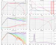
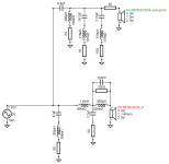
I was thinking along similar lines and dropped in an all-pass filter along with a normal IIR lowpass filter on the bottom woofer at the back of the cabinet and got responses like this:


This is just one example of a possibility and is close to what can be achieved with what I had done earlier using FIR filters. I haven't done any optimization on this.
The biquad coefficients on the all pass filter block look like this for the above

By tweaking the all-pass filter and the other filters one can realize different directivity slopes in the below 300Hz region like in the FIR linear phase filter case.
However, there is a catch. The excess group delay climbs rapidly below 100Hz, which was not much of an issue with the FIR filters earlier.
So I don't know what it will sound like compared to the other kind of filtering (as this excess group delay rise is supposedly bad?)
Anyway, I just thought I would share this here 🙂
And wishing a happy new year in advance to everyone.. 🙂
In my line of work, people are interested in realizing IIR digital filters with linear phase characteristics in the passband.
There are even many papers which specify ways of doing this using IIR filters + all pass filter cascades, even optimized algorithms for doing this since long back. Just an example here: https://www.advsolned.com/linear-phase-iir-filters-analysis-design/
I was thinking along similar lines and dropped in an all-pass filter along with a normal IIR lowpass filter on the bottom woofer at the back of the cabinet and got responses like this:
This is just one example of a possibility and is close to what can be achieved with what I had done earlier using FIR filters. I haven't done any optimization on this.
The biquad coefficients on the all pass filter block look like this for the above
By tweaking the all-pass filter and the other filters one can realize different directivity slopes in the below 300Hz region like in the FIR linear phase filter case.
However, there is a catch. The excess group delay climbs rapidly below 100Hz, which was not much of an issue with the FIR filters earlier.
So I don't know what it will sound like compared to the other kind of filtering (as this excess group delay rise is supposedly bad?)
Anyway, I just thought I would share this here 🙂
And wishing a happy new year in advance to everyone.. 🙂
@vineethkumar01
Did you model your coaxial midrange cardioid in ATH/ABEC using the BEE function before building your foam version or did you go straight to the foam version without simulations? I was wondering if BEE simulations got you close to your final design. Also, what was the difference between your final foam BEE design and the final round version you used in your final project. Trying to figure out the best approach after your experience.
Did you model your coaxial midrange cardioid in ATH/ABEC using the BEE function before building your foam version or did you go straight to the foam version without simulations? I was wondering if BEE simulations got you close to your final design. Also, what was the difference between your final foam BEE design and the final round version you used in your final project. Trying to figure out the best approach after your experience.
@CinnamonRolls
I didn't model the coaxial driver midrange cardioid exactly in ATH/ABEC.
But I did some ATH/ABEC simulations with a generic 5-inch diameter driver and iterated along with the foam core prototype (especially in changing the damping and overall cabinet dimensions part). The simulations definitely helped me in iterating this concept, I would say. But not probably in giving the exact idea about the damping part. This was found by trial and error (sort of).
Here are the BEM sims and the comparisons with results obtained using the prototype
BEM sim-1 (No damping)

predicted polars

Prototype-1

Measured polars

BEM sim-2 (with damping = 0.5)

Predicted polars

Prototype-2

Measured polars

Now that I could see the polars improving with the addition of damping, I added maximum possible damping (but damping uniformly distributed in the slot) and made prototype-3
Prototype-3

Measured polars

With the final design, my design considerations were the following:
1) A nice-looking cabinet that houses this cardioid concept along with space & dimensions for a woofer/subwoofer. I wanted the cabinet to get out of the way at the backside of the coax driver. I thought that since the radiation to the backside is anyway less due to the cardioid, having a curved/rounded shape getting out of the way of whatever little energy that goes to the back might further help with less reflections/diffraction. Hence the significantly rounded shape of the cabinet, with the rounding starting right at the place where the coax holding part joins the main cabinet. In both the teardrop cabinet build for this driver and with the teardrop shaped (in horizontal plane) 2way top module for my SB acoustics 3-way main system, I had seen that this kind of rounded cainet shape, (which I just created using splines) helped with smooth directivity curves.
I had tried to do an ABEC sim of this cabinet but gave up soon due to the learning curve/complexity involved 😀
Final speaker top-view

Final speaker: horizontal polar (unnormalized)

2) Sort of smooth termination of the waveguide formed by the mid driver for the coax tweeter. This was the objective behind the rounded ring frame that holds the coax, with the rounding starting right at the driver frame. I had found that this sort of rounding helps to some extent in my previous teardrop cabinet build for this coax driver.
Edit: Please find attached the final cabinet stl file that I had used to build this cabinet, just in case you want to take a look at it
I didn't model the coaxial driver midrange cardioid exactly in ATH/ABEC.
But I did some ATH/ABEC simulations with a generic 5-inch diameter driver and iterated along with the foam core prototype (especially in changing the damping and overall cabinet dimensions part). The simulations definitely helped me in iterating this concept, I would say. But not probably in giving the exact idea about the damping part. This was found by trial and error (sort of).
Here are the BEM sims and the comparisons with results obtained using the prototype
BEM sim-1 (No damping)
predicted polars
Prototype-1
Measured polars
BEM sim-2 (with damping = 0.5)
Predicted polars
Prototype-2
Measured polars
Now that I could see the polars improving with the addition of damping, I added maximum possible damping (but damping uniformly distributed in the slot) and made prototype-3
Prototype-3
Measured polars
With the final design, my design considerations were the following:
1) A nice-looking cabinet that houses this cardioid concept along with space & dimensions for a woofer/subwoofer. I wanted the cabinet to get out of the way at the backside of the coax driver. I thought that since the radiation to the backside is anyway less due to the cardioid, having a curved/rounded shape getting out of the way of whatever little energy that goes to the back might further help with less reflections/diffraction. Hence the significantly rounded shape of the cabinet, with the rounding starting right at the place where the coax holding part joins the main cabinet. In both the teardrop cabinet build for this driver and with the teardrop shaped (in horizontal plane) 2way top module for my SB acoustics 3-way main system, I had seen that this kind of rounded cainet shape, (which I just created using splines) helped with smooth directivity curves.
I had tried to do an ABEC sim of this cabinet but gave up soon due to the learning curve/complexity involved 😀
Final speaker top-view
Final speaker: horizontal polar (unnormalized)
2) Sort of smooth termination of the waveguide formed by the mid driver for the coax tweeter. This was the objective behind the rounded ring frame that holds the coax, with the rounding starting right at the driver frame. I had found that this sort of rounding helps to some extent in my previous teardrop cabinet build for this coax driver.
Edit: Please find attached the final cabinet stl file that I had used to build this cabinet, just in case you want to take a look at it
Attachments
Last edited:
@vineethkumar01
Nice- Practice makes progress!
I'm curious about the attenuation at 90°, in an attempt to minimize side wall reflections.
Your attenuation 90° appears to be about -10 to -12dB.
Do you think there's anyway to attenuate further, whilst maintaining a -6dB beamwidth of ~60°?
Nice- Practice makes progress!
I'm curious about the attenuation at 90°, in an attempt to minimize side wall reflections.
Your attenuation 90° appears to be about -10 to -12dB.
Do you think there's anyway to attenuate further, whilst maintaining a -6dB beamwidth of ~60°?
For reduction in energy radiating to 90 degrees, I think the best solution is a full range (ish) dipole.
But it has other compromises to take care of, like placement.
So I haven't explored that concept much yet (though I remember about a good experience with a full-range driver in an open baffle long long back).
Using passive techniques like passive cardioid, I don't much know how to control radiation unless we use specifically designed waveguides/horns for that purposes.
But for an active implementation, something that I had been going back again and again and referring to is creating driver arrays.. 🙂
This one has been a long time reference for me. I keep going back and referring to it time and again but never got a chance to build/incorporate the concepts used in one of my builds yet.. 😀
I feel that it is a smart piece of engineering (along with everything else FoLLgoTT has done 😀):
http://loudspeaker-research.de/Quasikoax 1 Documentation.pdf
This along with an active bass stearable module for below 500Hz could do the job of pattern control down to low frequencies, I think
Some day, I will explore something along these lines.. 😉
Till the big speakers are ready, I am planning to use my small SB15CAC30-8 woofer + SB26CDC on 4inch augerpro waveguide speaker (5.5L internal volume) as my TV unit speakers (I got a Sony Bravia X74L 55inch TV few days back 😀 )
Speaker has teardrop-ish shape in horizontal plane and looks like this:


For convenience, I designed a passive crossover like this


Reverse null (although the phase matching at crossover is visible in 6pack above)

Preference ratings

WIth a big series cap on the woofer, the response look like this


Comparison with & without series capacitor (blue curve is the on axis response without series capacitor)

Please do let me know your opinions about this design
Speaker has teardrop-ish shape in horizontal plane and looks like this:
For convenience, I designed a passive crossover like this
Reverse null (although the phase matching at crossover is visible in 6pack above)
Preference ratings
WIth a big series cap on the woofer, the response look like this
Comparison with & without series capacitor (blue curve is the on axis response without series capacitor)
Please do let me know your opinions about this design
The locally available 1.75mH inductor has about 0.7ohm DCR
https://theaudiocrafts.com/x-over-p...ors/18-awg-air-core-inductor-lw-series?page=2
https://theaudiocrafts.com/x-over-p...ors/18-awg-air-core-inductor-lw-series?page=2
I think the impedance in the treble could be a bit problematic for some amps. Try to get rid of the 4ohm shunting resistor?
The bump followed by broad dip of SB17CAC35 in the 1st filter version is something of concern to me. Have you experimenten to make more flat without the large capacitor? I see it is a sealed box, so the Qts may be too high?
You could try an impedance flattening LCR for the woofer resonance to see how that influences the bass too. Needs large value coils and caps though, but DCR/ESR is not critical.
your woofer’s series inductor DCR is little high. Lowering it to 0.3ohm may help a little but the midrange/treble may still be on the high side. Depending on speaker placement I feel you need a bit more BSC:
I agree... if you could find a steel-core inductor wound with 16 gage wire, that would be great.your woofer’s series inductor DCR is little high
Depending on speaker placement and room acoustics, I feel you may need a bit more BSC: eg.

@tktran303 ,@Rallyfinnen @JanRSmit ,@hifijim : Thanks very much for the suggestions 🙂
The cabinet volume for this speaker was never really intended to let the SB15CAC driver play maximum low end. It was intended to be for that driver to act as a midrange in a 3way setup with the 2xSatori WO24P-8 acting as the woofers. So the box it not having an optimal Qts for an application like this.. I am just trying to make do with this box.
I have replaced the air core woofer inductor with16AWG steel laminated core one having a low DCR. Here are the results of crossver-v2


Reverse null

The cabinet volume for this speaker was never really intended to let the SB15CAC driver play maximum low end. It was intended to be for that driver to act as a midrange in a 3way setup with the 2xSatori WO24P-8 acting as the woofers. So the box it not having an optimal Qts for an application like this.. I am just trying to make do with this box.
I have replaced the air core woofer inductor with16AWG steel laminated core one having a low DCR. Here are the results of crossver-v2
Reverse null
Attachments
The enclosure volume mismatch explains the bump at ~120hz, the whole looks better, except for the broad plateau from ~500 to ~3000hz being a 1-2 db too loud, My first hunch is to tame the output of the bass/mid in that region.
The impedance dip at 11khz is still low in my view.
The impedance dip at 11khz is still low in my view.
- Home
- Loudspeakers
- Multi-Way
- A 3 way design study