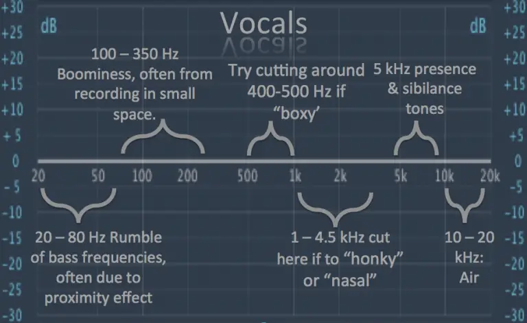
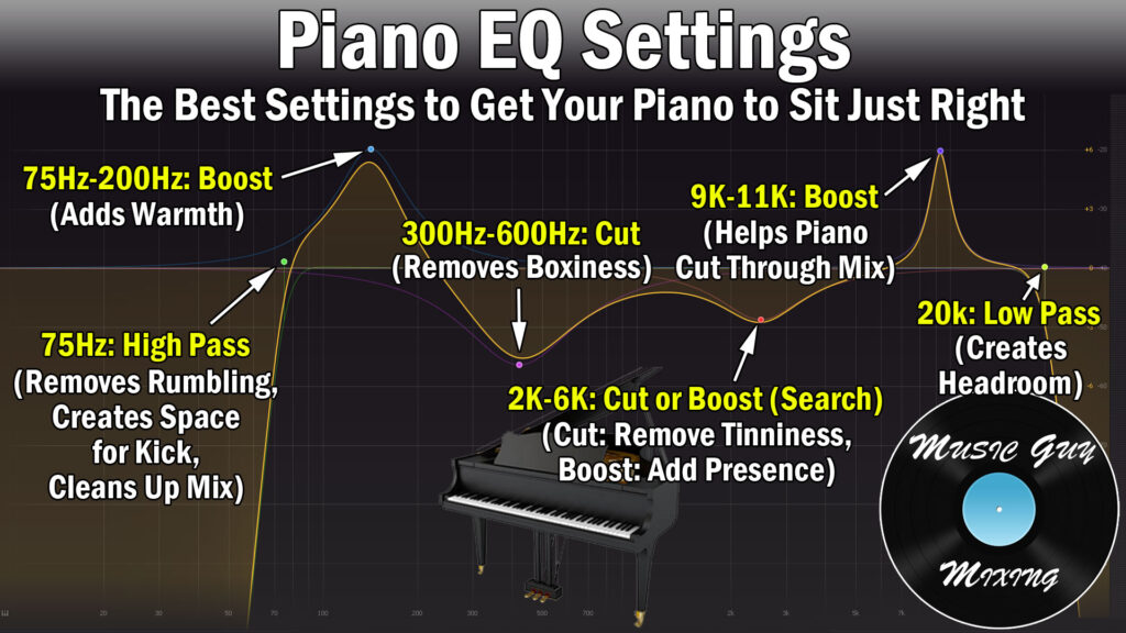
A boxy sound can mean a lot of different things to many people 😉. But in music production it's almost always a sign that there's too high of a level around 500-600 Hz.
No matter what the instrument is:

This does not have to be a problem that is specific for a woofer in a closed box. When properly designed it should not have to sound boxy.
I'd agree that different type of speakers have a different sound in-room. When there's less early reflections in the room, some things/frequency ranges could stand out more and stuff like that can even create a boxy sound or sibilance problems.
No matter what the instrument is:
This does not have to be a problem that is specific for a woofer in a closed box. When properly designed it should not have to sound boxy.
I'd agree that different type of speakers have a different sound in-room. When there's less early reflections in the room, some things/frequency ranges could stand out more and stuff like that can even create a boxy sound or sibilance problems.

I would like to go with as less volume for the cabinet as possible. The below explanation is the justification I had for allocating the volumes I mentioned above. Please take a look at and it and point out any flaws.I would go with a significantly smaller volume for the rear woofer. This woofer's radiation cancels the front woofer to create cardioid response. To get max low end extension in this scenario, equalize the front woofer down to 20 Hz or so but high pass the rear woofer at 50 Hz. If you are doing that, it doesn't need so much volume or volume displacement. With equal volumes and more elaborate DSP scheme, you could arrange rear woofer to be phased for cancellation above a transition frequency such as 50 Hz and in phase for support below that frequency. Transition frequency might be related to distance from front wall.
It seems like to have a front woofer DSP EQable to 20Hz calls for a different woofer than the one I have for the front woofer application (Faital pro 15PR400). That woofer just doesn't go low unless given big box volumes and then DSP EQed. But that again might be a compromise because of the low xmax of the woofer and potential for higher IMD due to its upper end extension needed up to about 1kHz (roughly). So my thoughts were to give it some box volume so that it doesn't needed to stress a lot but yet reach without much attenuation to 100 Hz. The 40L box gives this:
STATISTICS
f3 89.8 Hz
f6 68.3 Hz
f10 51.1 Hz
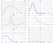
From the plots give a few posts above, I want it to look like the red curve in below pic
The real low-end extension (below 100Hz) is hopefully given by the subwoofer driver I have at the back of the box. Its transfer function is given by the green curve shown above.
This driver also serves the purpose of creating directivity/cancelling out the front woofers radiation to the back at low frequencies around 100-300Hz. For that it needs to go easily to 100Hz but then the SPLmax limitation of this entire system is also determined by the back driver.
If I chose the SB audience NERO SW800 subwoofer driver, it gives a response like below in a 42ish L box.
I am able to get a max SPL of 105dB at 30Hz
With the DSP EQ, the response changes to below:
STATISTICS
f3 26.7 Hz
f6 21.5 Hz
f10 17.6 Hz
With the above performance, the excursion seems to have reached close to 10mm for this driver which has a published xmax of 14mm.
And I think this itself is a stretch for this driver given that SB usually cheats with the xmax specs. They usually mention the peak to peak excursion instead of the one sided excursion, atleast in their home audio driver line. So most probably the linear xmax of this driver may also be close to 8mm I guess in the worst case.
Attachments

Last edited:
Boxy i've heard used wrt issues associated with reflections 'inside' the box ( standing waves and or very short delay surimposed to initial signal reproduced) which leaks outside ( through port or driver's membrane). It's often used by OB aficionados to explain what they dislike about other choices than their owns.
It doesn't really means anything: it's very subjective.
It doesn't really means anything: it's very subjective.
You are right not to expect low distortion near Xmax but if that only is reached on low bass peaks, its not so bad. There are certainly woofers available optimized for smaller boxes but even those are bound by Hoffman's iron law and will require more power to get to the same low end SPL. The 15PR400 isn't too bad in terms of its volume requirements. I would fault it more for its limited Xmax. I chose the Acoustic Elegance TD15H with 14 mm Xmax for similar application some time ago, but that would be expensive today and hard to get, especially where you are.
Include floor and wall image drivers in your Vituix simulations to see what boundary support/interference you will get with your planned placement. That bears upon the driver excursion analysis.
Given your front woofer has limited Xmax, it should only play perhaps 100 Hz or 125 Hz++. Then subwoofer plays 20 Hz to 250 Hz, allowing a cardioid-like response in the overlap region to avoid a front wall null. If this is your plan, then I would give more volume to the rear woofer, instead of what I said initially.
@vineethkumar01 - I notice that you use the L-T function in Vcad to extend the bass. I never use that function, instead I use a 2nd order shelf function to achieve the same result. The reason I do this, is because it allows me to explicitly control how much boost I apply in the deep bass.
As a starting point, I usually set the Q of the shelf filter to be equal to the Qtc of the sealed box woofer. If I want to apply 6 dB of boost, I examine the un-EQ'd response curve and find the - 6 dB point. I adjust the shelf filter frequency so that + 6 dB of boost happens at that same frequency.
As a starting point, I usually set the Q of the shelf filter to be equal to the Qtc of the sealed box woofer. If I want to apply 6 dB of boost, I examine the un-EQ'd response curve and find the - 6 dB point. I adjust the shelf filter frequency so that + 6 dB of boost happens at that same frequency.
I am planning to use the 15PR400 (which I already have in hand) as the front woofer and an SB audience NERO SW800 tentatively due to cost and the non-availability of brands like BMS here. (https://www.sbaudience.com/index.php/products/subwoofers/nero-15sw800/) as the back woofer. This one has a 14mm xmax.You are right not to expect low distortion near Xmax but if that only is reached on low bass peaks, its not so bad. There are certainly woofers available optimized for smaller boxes but even those are bound by Hoffman's iron law and will require more power to get to the same low end SPL. The 15PR400 isn't too bad in terms of its volume requirements. I would fault it more for its limited Xmax. I chose the Acoustic Elegance TD15H with 14 mm Xmax for similar application some time ago, but that would be expensive today and hard to get, especially where you are.
I am very interested in such an analysis, could you point me to some link or any place where I can read up more about how to do this?Include floor and wall image drivers in your Vituix simulations to see what boundary support/interference you will get with your planned placement. That bears upon the driver excursion analysis.
This is exactly what I had in mind. But I would still like to see if the volume of the entire cabinet can be reduced without much performance penalty..Given your front woofer has limited Xmax, it should only play perhaps 100 Hz or 125 Hz++. Then subwoofer plays 20 Hz to 250 Hz, allowing a cardioid-like response in the overlap region to avoid a front wall null. If this is your plan, then I would give more volume to the rear woofer, instead of what I said initially.
As an example... here is the SB Audience Nero 15SW800 in a 40 liter sealed boxinstead I use a 2nd order shelf function to achieve the same result
Now I enable a 2nd order shelf filter, with a Q = 0.63 since that is the Qtc of the woofer+box. Normally, I use about +6 dB of boost, but this is no ordinary driver. This massive driver has huge excursion and power ability, so I set the boost (gain) of the filter at +10dB. Next I adjust the frequency of the filter until I get a flat response with a smooth rolloff... I started at 25 Hz and moved up until I found 38 Hz gave the nicest response. Now F3 = 36.2 and F6 = 27.5 Hz. Notice that group delay is improved in the range from 50-200 Hz.
If we bump up the power and SPL we can see where this woofer runs out of steam. For music applications, I usually assume there is little musical content below 30 Hz, so I simulate hitting Xmax at 30 Hz. If this was a home theatre application, I would probably go with something lower (25 Hz perhaps?)
At Xmax at 30 Hz, we hit 110 dB SPL, and it takes about 700 W to do it.
Anyway... that is how I do a Linkwitz Transform EQ with a sealed box woofer.
j.
the Murphy Corner Line Array is a good reference for understanding basic principles of image drivers.I am planning to use the 15PR400 (which I already have in hand) as the front woofer and an SB audience NERO SW800 tentatively due to cost and the non-availability of brands like BMS here. (https://www.sbaudience.com/index.php/products/subwoofers/nero-15sw800/) as the back woofer. This one has a 14mm xmax.
I am very interested in such an analysis, could you point me to some link or any place where I can read up more about how to do this?
This is exactly what I had in mind. But I would still like to see if the volume of the entire cabinet can be reduced without much performance penalty..
Murphy Corner Line Array
In Vituix, you simply insert another instance of a driver whose reflection you want included in the calculated response,, instead of just in the in-room response with its reflection enabled. Take a front facing woofer whose center is 250 mm above the floor and 750 mm below 0 (tweeter level). The mirror image of the driver will be 250 mm below the floor, so its "Y" in Vituix will be -1250mm. Visualize creating the image by tilting the woofer back 180 degrees, then rotating it 180 degrees to face front. Thus, "T" and "R" for the Vituix instance are both 180.
You can also do the same/similar thing for the front wall reflection. This would be especially beneficial for your rear subwoofer. Be careful though since your walls become transparent to bass below some frequency (perhaps 30-40 Hz) if not solidly constructed.
In design, you cross the woofer over before its reflection (image output) transitions from support to interference. In comparing system sim to enclosure sim, you find you need 6 db less power and correspondingly less excursion to get to you target maxSPL. If you do the floor image for an elevated front woofer, you will immediately see if there is a floor null within its passband and perhaps mitigate in the crossover or by changing driver elevation.
@nc535: Thanks.. 🙂 I will try definitely out the method you mentioned..
In other news, I am slowly trying different approaches to make myself like the rectangular box design.. 😀


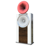
I decided to make it a modular two-box solution for portability, ease of handling, measurements and modification of system concept, for example, modifying the tweeter-horn module to something like the GGNTKT speaker, in future if needed. 🙂

In other news, I am slowly trying different approaches to make myself like the rectangular box design.. 😀
I decided to make it a modular two-box solution for portability, ease of handling, measurements and modification of system concept, for example, modifying the tweeter-horn module to something like the GGNTKT speaker, in future if needed. 🙂
Thank you for showing this, Jim. After seeing your earlier post yesterday, I tried this method without success. That seemed odd, since the concept of invert & add was both simple & sensible!Anyway... that is how I do a Linkwitz Transform EQ with a sealed box woofer.
The difference was obvious once I saw the new graphs. I have "show effect of inductance" turned on, so there are more interactions in play. Getting a flat response hasn't been so quick, at least with the few drivers I've tried. Even with inductance disabled, the high-Qtc alignment I just tested did require additional EQ.
It's a neat idea, and I'll keep playing with it. I suppose I'm posting mainly to keep others from losing too much hair if they can't match your results immediately.
I tried to include the floor and front wall image sources into the simulation (to the best of my current understanding)


There are a few points & questions I noted from above.
1) The image sources affects the polar pattern (other than affecting the subwoofer EQ requirements). With the above kind of filtering applied to the front and back drivers, I am only able to get a directivity as shown above.
2) Thic configuration gives an amount of attenutation to the rear 90 degrees ranging from about 9 dB at +/-135 degrees in the horizontal plane reaching up to 30ish dB of attenuation at 180 degrees between 100 to 200Hz. Below that the radiation is omni.
Here are polar diagrams at (approx) 100 degrees, 150 degrees, and 200 degrees


The radiation is truly cardioid only around 150Hz.
3) The attenuation of radiation to the rear 90 degrees stays constant ish at an average attenuation of about 9 dB in the octave ranging from 250 to 500Hz. Beyond that anyway the 15inch woofer size and baffle size (50cm width) start to dominantly affect the directivity.
Polar pattern around 400Hz

4) Is the above kind of polar pattern worth pursuing? (in the sense that will it give enough attenuation of the rear radiation to make a significant difference in sound)
5) I am worried about the excess group delay rising to about 3.7ms at 100Hz. Is this problematic?
If so, can anything be done about this?
6) The vertical polar pattern looks frightening 😀 But I am hoping that the smooth looking power response is what we will hear and hence the entire setup wont be a problem
I have attached the VituixCAD project if anyone wants to take a look.
There are a few points & questions I noted from above.
1) The image sources affects the polar pattern (other than affecting the subwoofer EQ requirements). With the above kind of filtering applied to the front and back drivers, I am only able to get a directivity as shown above.
2) Thic configuration gives an amount of attenutation to the rear 90 degrees ranging from about 9 dB at +/-135 degrees in the horizontal plane reaching up to 30ish dB of attenuation at 180 degrees between 100 to 200Hz. Below that the radiation is omni.
Here are polar diagrams at (approx) 100 degrees, 150 degrees, and 200 degrees
The radiation is truly cardioid only around 150Hz.
3) The attenuation of radiation to the rear 90 degrees stays constant ish at an average attenuation of about 9 dB in the octave ranging from 250 to 500Hz. Beyond that anyway the 15inch woofer size and baffle size (50cm width) start to dominantly affect the directivity.
Polar pattern around 400Hz
4) Is the above kind of polar pattern worth pursuing? (in the sense that will it give enough attenuation of the rear radiation to make a significant difference in sound)
5) I am worried about the excess group delay rising to about 3.7ms at 100Hz. Is this problematic?
If so, can anything be done about this?
6) The vertical polar pattern looks frightening 😀 But I am hoping that the smooth looking power response is what we will hear and hence the entire setup wont be a problem
I have attached the VituixCAD project if anyone wants to take a look.
Attachments
The reason for including the images is because the reflections they model are early reflections and thus heard as part of the direct sound. Furthermore, they are so low in frequency, they can't be absorbed. Thus, its best to include their response in your crossover.
The vertical polar map is indeed frightening; it seems to be giving you the evil eye. 🙂
If you let the rear woofer overlap up to 300 Hz or so and tune its phase and amplitude in the overlap region, you should be able to improve it.
You could make up the sensitivity loss by crossing over to the subwoofer sooner.
BTW: I have found its best to be looking at the H line chart when making small directivity tweaks
Has anyone tried manipulating a program like RePhase or DIRAC to trick it into creating perfect cardioid behavior or am I missing a physics lesson here?
Despite what nc535 suggested, my advice would be that you design the speaker with semi-anechoic or equivalent measurements and then see what you get in the listening position in the room and modify accordingly.There are a few points & questions I noted from above.
but take the boundary support into consideration when deciding how much woofer excursion you needDespite what nc535 suggested, my advice would be that you design the speaker with semi-anechoic or equivalent measurements and then see what you get in the listening position in the room and modify accordingly.
I have those image drivers in the model but I mute/unmute them depending on what I'm doing
Once you have measurements they will of course stay muted
Once you have measurements they will of course stay muted
- Home
- Loudspeakers
- Multi-Way
- A 3 way design study