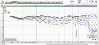
To have some more confidence with measurements and to have some sort of a reference before doing some experiments, I measured my Q Acoustics 2020i speakers today (Quasi anechoic gated at 3.7ms + nearfield wit baffle step correction applied and merged).
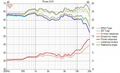
Attached pics show how the far field response looks like and the power response directivity etc from VituixCAD.
🙂
Attached pics show how the far field response looks like and the power response directivity etc from VituixCAD.
🙂
Attachments
Hi,
@augerpro, I got some doubts while i was reading through the last part of the box construction methods section on your website. Could you pleade help me understand more about this. I have taken a few pictures from there and attached it with this post. I hope it s ok.
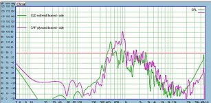
In the first pic the comparison is between the CLD mdf plus mdf, CLD braced box and the 3/4 inch plywood box. I am interested in the 100Hz to 400 Hz region here since i am thinking about a woofer cabinet in a 3 way. The plot says that the rear radiation from the CLD box is more silent. Comparing with the next plot which shows reaults for the side radiation from the same box, it looks like the plywood box is more silent here. Could you tell me more about why this is so. It is because of more surface area of the sides combined than the rear. Or is it because therear of the cabinet is further away compared to the sides so that it lesser energy reaches the back?
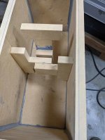
Another question that i have is regarding thd 3rd pic of the CLD box. Could you please tell me the dimensions of the box and how the bracing scheme is fixed. That is how far apart should be a set of braces (By a set of braces, i mean the four parts of the brace, each of which attaches to a wall of the box).
Also, are all the four pieces of a set joined together at the middle for thd 33% overlap. Also how are the braces joined to the sides. Is it using a regular glue or the glue used for CLD application. And how is the brace joined to the front panel of the box. Is it using the same glue?
Thanks
Vineeth
@augerpro, I got some doubts while i was reading through the last part of the box construction methods section on your website. Could you pleade help me understand more about this. I have taken a few pictures from there and attached it with this post. I hope it s ok.
In the first pic the comparison is between the CLD mdf plus mdf, CLD braced box and the 3/4 inch plywood box. I am interested in the 100Hz to 400 Hz region here since i am thinking about a woofer cabinet in a 3 way. The plot says that the rear radiation from the CLD box is more silent. Comparing with the next plot which shows reaults for the side radiation from the same box, it looks like the plywood box is more silent here. Could you tell me more about why this is so. It is because of more surface area of the sides combined than the rear. Or is it because therear of the cabinet is further away compared to the sides so that it lesser energy reaches the back?
Another question that i have is regarding thd 3rd pic of the CLD box. Could you please tell me the dimensions of the box and how the bracing scheme is fixed. That is how far apart should be a set of braces (By a set of braces, i mean the four parts of the brace, each of which attaches to a wall of the box).
Also, are all the four pieces of a set joined together at the middle for thd 33% overlap. Also how are the braces joined to the sides. Is it using a regular glue or the glue used for CLD application. And how is the brace joined to the front panel of the box. Is it using the same glue?
Thanks
Vineeth
Attachments

Last edited:
Good questions! So don't look at anything below about 200hz, the noise floor starts to dominate there. I note this at the beginning of the tests, but I should probably restate measurement conditions whenever I post new info just to remind people.
I'm not exactly sure why the rear and side are different, that's why I just do both. What I can say is that that the rear panel is narrower, which should be stiffer - all other things equal. Sometimes I think that fact dominates the results over other variables, and so for me personally I like the side panel results as better showing the differences between materials and methods. At frequencies below the primary resonances I don't think distance from the driver has anything to do with it, it's just pressure and that is distributed evenly. Sorry I can't add more to that. I will say though that the primary resonances from about 400-1200hz should be your deciding factor. The spl is very high at those frequencies. At 200hz the levels are so low in any braced box that I'm not sure it matters if one methods looks a little better than the other.
Dimensions IIRC are 18"h x 8"w x 10"d.
Originally I used % overlap for the braces but I think the correct way to look at is the length of overlap, which would be related to the surface area of the constrained layer doing the actual work. I used 2" overlap in the example above. Too much overlap and it quickly acts like a solid brace. I have not investigated any beyond that so I don't know how other box constructions might behave differently. I did size this box to be between a standmount and woofer section of the 3-way so that results should generally be similar in those applications. But if say you were building a large subwoofer I really don't know how the overlap should be handled. Then again I would probably solid brace a sub, so maybe a bad example.
Obviously the constrained layer is the Weicon 310M Flex. I debated what to use to attach the braces to the walls and in the end I use regular wood glue. My thinking was this: I want a rigid attachment to the walls so the energy can be efficiently directed to the constrained layer. The other approach using Weicon at all connections would have different masses sort of "detached" from each other and I'm not sure how you would predict the outcome. That was my thinking for what it's worth.
A change I made with that particular example is making a T-shape instead of the simple straight "dowel" I used before. Again the thinking was by having the brace "see" more surface area of the panel, more energy would be directed to the constrained layer. Again, take that for what it is worth.
Last edited:
Also, in any actual build, I think I would use 3/4" plywood for the braces, regardless of what the rest of the box is made from. Again I'm thinking efficiently transferring energy through the rigid brace/box to the constrained layer. I just didn't have plywood when I built these boxes.
Thank you for all these details. This is exactly the kind of information I was looking for. 🙂
So with the dimensions of the box that you specified, the rough internal volume of the box is about 20 litres. I am looking for box with internal volume of about 35 litres as per the specs of my woofer. But as per the specs of my baffle, it will be slightly wider and slightly more deeper and probably a little bit more in height that the box you specified. In such a scenario, would putting 2 sets of braces (all 4 pieces is one set) and 1/3rd and 2/3rd distances along the height dimension a good approach?
The other doubt I had is you had also mentioned about the easy method for driver mounting in the website, where screws were used along with rubber washers to attach drivers on the baffle. Do you have any pics showing these washers and how they are attached to the driver?
The other doubt I had is regarding making the CLD panel itself. Since I would be trying to make bigger panels for the box, is it better to glue up the two layers with the CLD glue first and then cut it to required size or cut them first and then attach them together. I am asking this since a friend of mine who has access to these cutting tools remarked that cutting through glued panels can damage the blades of the cutting equipment etc.
Also, do you have any recommendations regarding making a CLD front baffle?
And what is a good material for the baffle?
I keep reading about people making baffles out of sandwich of different materials like wood+MDF, HDF alone, MDF+plywood, and even laminated bamboo lumber. I keep hearing that the front panels need to be stiff so that it acts as a good launch platform for the drivers.
My baffle as per current plans would be about 2 inches thick for cutting out the chamfers etc. I am a bit confused about all these choices for building a baffle.
If you are doing one set of braces I would put them in the center of the panel for best results. With 2 sets, I'm not sure. There are differing opinions on that like not using equal spacing (so 1/3 and 2/3 is out), but that might be overthinking it a bit. I personally would go closer to the center than 1/3 and 2/3, maybe more like 40% and 60%.
I don't have any pics of the rubber washers. Just something I grabbed at the hardware store. They also had Viton o-rings and you could probably use those too. I think Viton is a good vibration damper.
I glue the panels up first then cut to size. Well, sort of, I actually rough cut some oversize sections, an inch over the width of the panel you need, and the length of the sheet. Makes for more manageable pieces and working time when you glue them up. Then you are just trimming some excess when you cut to final dimensions. I don't think that adhesive you found should be hard on the blades. It's way softer than wood.
Personally I would just build the baffle like I do the rest of the box.
If you are doing one set of braces I would put them in the center of the panel for best results. With 2 sets, I'm not sure. There are differing opinions on that like not using equal spacing (so 1/3 and 2/3 is out), but that might be overthinking it a bit. I personally would go closer to the center than 1/3 and 2/3, maybe more like 40% and 60%.
I don't have any pics of the rubber washers. Just something I grabbed at the hardware store. They also had Viton o-rings and you could probably use those too. I think Viton is a good vibration damper.
I glue the panels up first then cut to size. Well, sort of, I actually rough cut some oversize sections, an inch over the width of the panel you need, and the length of the sheet. Makes for more manageable pieces and working time when you glue them up. Then you are just trimming some excess when you cut to final dimensions. I don't think that adhesive you found should be hard on the blades. It's way softer than wood.
Personally I would just build the baffle like I do the rest of the box.
Thanks a lot. I will keep these suggestions in mind. 🙂
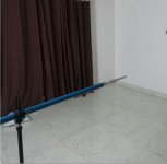
The most important part of all of this is your measurement setup. It has to be clean and accurate. So make sure you work that out. the mic should just be sticking out the end of the boom or you will get diffraction off those holders on a typical mic stand. Get everything as equid-distant from the floor/ceiling/walls as possible so you can maximize your gate. Your splicing method looks like the one I use and it works real well as long as you sweat all the details.
Thank you. I will take a lot of care with the measurement setup next time I do it.
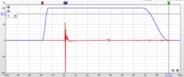
My current measurement mic setup looks like pic-1. the mic is attached to a 1m long pvc pipe. Recently i have also tried to make transition from pvc pipe to mic also smoother instead of a sudden 3mm thick edge of the pipe. I have two rooms an almost 3m x 3m x 4m one and another one with almost 3m x 3m x 7m dimensions available for measurements. I will try to ensure minimizing floor and ceiling reflections next time. With current setup, I can get impulse responses like in pic 2 but in it the speaker was not exactly at mid height between floor and ceiling.
Currently I use nearfield + gated farfield measurements. But once I start taking woofer measurements, I may need to go for ground plane or much bigger rooms etc as per suggestions given by others. I will have to figure it out later.
Attachments
Yeah that's a good mic setup.
Forget about minimizing reflections. It will never be enough. Focus on getting the largest distance possible from all boundaries, then set your gate to end before the first reflection arrives. Do you have a garage? Often the ceiling is taller in a garage than a room in the house. That might get you into the 5-7us window of reflection free sound.
Forget about minimizing reflections. It will never be enough. Focus on getting the largest distance possible from all boundaries, then set your gate to end before the first reflection arrives. Do you have a garage? Often the ceiling is taller in a garage than a room in the house. That might get you into the 5-7us window of reflection free sound.
Unfortunately, I live in an apartment complex in a concrete jungle of a place. 🙂
It is hard to find open spaces here and a time when all sources of noises are silent. So these days, I try to do measurements at night. I do have access to a car parking place with probably 3.5m high ceilings but it is usually filled with a lot of vehicles. Another option I have is the roof of the four storey apartment. This I will need to try out and see if it works for a better gate duration in measurements.
I will try to ask around and try to hopefully get a better place once the speaker cabinet is built by a friend who has access to tools, CNC cutting, and more experience in building speakers cabinets. If all goes well and I am able to finalize the design with all details, the cabinet building process will start by the end of this month.. 🙂
vineethkumar - I went to the effort (a significant effort) of making high resolution outdoor ground plane measurements of both a large woofer and a midwoofer. I was ~7 meters from the nearest wall, I waited for quiet periods with no wind, and I was able to get resolution down to 10 Hz.
What I found is that the Near Field technique is very accurate. When I made indoor NF measurements and then adjusted the response from 2-pi to 4 pi, my NF measurements very closely matched the outdoor ground plane measurement.
see post #124
https://www.diyaudio.com/forums/multi-way/366347-active-satori-textreme-13.html#post6565109
In the future, I will not bother with outdoor ground plane measurements.
j.
vineethkumar - I went to the effort (a significant effort) of making high resolution outdoor ground plane measurements of both a large woofer and a midwoofer. I was ~7 meters from the nearest wall, I waited for quiet periods with no wind, and I was able to get resolution down to 10 Hz.
What I found is that the Near Field technique is very accurate. When I made indoor NF measurements and then adjusted the response from 2-pi to 4 pi, my NF measurements very closely matched the outdoor ground plane measurement.
see post #124
https://www.diyaudio.com/forums/multi-way/366347-active-satori-textreme-13.html#post6565109
In the future, I will not bother with outdoor ground plane measurements.
j.
Thanks a lot for this information. I will also try nearfield method first. I was worried about the woofer-mid crossover design as my baffle wouldn't exactly be flat due to chamfers and VituixCAD currently doesn't allow modeling diffraction effects due to chamfers. I thought that this would make applying baffle-related effects on the 2pi-nearfield measurement may not be accurate. Now I am thinking that maybe because the wavelengths concerned are large enough in that frequency range the chamfers may not have any effect as they have in the case of the tweeter response.
Thanks again... 🙂
I will try this out once I am able to make the speaker boxes and start taking measurements.
After reading the discussion about midranges over at hifijim's project, I am wondering about the choice of my midrange (SB15CAC30-8). Since my cabinet has not yet been built, I still have the option of continuing with another midrange driver if it makes a significant improvement to the overall project and shelve the current driver for another project.
In this regard, could anyone tell me more about the (5inch, 4inch) midrange choices that I have, which could be used with the WO24P-8 woofer and the SB26CDC004 tweeter?
What improvements are possible subjectively with a dedicated midrange. Locally available drivers include Satori MW13P (MR13P not available at the moment), Wavecor WF120BD03 (and some other wavecors), Dayton RS125, RS100, Dayton AN-52 dome midrange, Hivi Dome midrange, Peerless NE123, Peerless NE95, BMS 5S117, Faitalpro 5FE120, etc. Please post your thoughts
Thanks
Vineeth
Last edited:
I wouldn't take any of those over the SB15CAC, maybe the Satori or Wavecor, but I'd have to compare measurements to even determine that. I also disagree with Juhazi's position on this driver that you are probably referring to. To the extent that the surround contributes to distortion as claimed, then I would compare the actual measurements of HD and IMD of the SB15CAC to the ones you list. You'll find it's clean clean clean, especially in a midrange application.
And from rational point of view one should remember there is always path to upgrade until the end of days, so better stick what we already have and get the current job done. And I bet improvement on sound swapping drivers is insignificant in comparison to gained knowledge on how to actually design and build speakers. On the next project you have opportunity to utilize the knowledge, as well as different drivers, if you will. Have fun!🙂
I wouldn't take any of those over the SB15CAC, maybe the Satori or Wavecor, but I'd have to compare measurements to even determine that. I also disagree with Juhazi's position on this driver that you are probably referring to. To the extent that the surround contributes to distortion as claimed, then I would compare the actual measurements of HD and IMD of the SB15CAC to the ones you list. You'll find it's clean clean clean, especially in a midrange application.
My thoughts exactly... I'm using. My phone so I must be brief... I like the sb15cac a lot
I have had my eye on the Wavecor drivers for a while particularly the 120 and 152. The differences are not huge but one thing I notice when comparing the normalized off axis graphs at Hificompass is that the Wavecor 120 has a smoother and more even off axis response as frequency rises and it's breakup is much better controlled.What improvements are possible subjectively with a dedicated midrange. Locally available drivers include Satori MW13P (MR13P not available at the moment), Wavecor WF120BD03 (and some other wavecors), Dayton RS125, RS100, Dayton AN-52 dome midrange, Hivi Dome midrange, Peerless NE123, Peerless NE95, BMS 5S117, Faitalpro 5FE120, etc. Please post your thoughts
Thanks
Vineeth
You may have seen but Alexander Heismann has used some of the Wavecor drivers and they have superb directivity and burst decay in a very similar baffle to what you have shown.
DXT-MON | 5 ″ 1 ″ | Near field monitor | Compact speaker
I could simulate your baffle for you in 3D to show the effect of the cabinet diffraction and chamfers. The lower chamfer has virtually no real effect but the split chamfer on the lower woofer can have a weird effect on directivity even at that frequency.
I don't really disagree with Jim's position on nearfield measurements but there is an effect from the whole cabinet particularly the depth which becomes more evident with full 360 degree measurements, particularly when the baffle is not flat all the way. It does take a lot of effort to measure it or some effort to simulate it though 🙂
I wouldn't take any of those over the SB15CAC, maybe the Satori or Wavecor, but I'd have to compare measurements to even determine that. I also disagree with Juhazi's position on this driver that you are probably referring to. To the extent that the surround contributes to distortion as claimed, then I would compare the actual measurements of HD and IMD of the SB15CAC to the ones you list. You'll find it's clean clean clean, especially in a midrange application.
And from rational point of view one should remember there is always path to upgrade until the end of days, so better stick what we already have and get the current job done. And I bet improvement on sound swapping drivers is insignificant in comparison to gained knowledge on how to actually design and build speakers. On the next project you have opportunity to utilize the knowledge, as well as different drivers, if you will. Have fun!🙂
My thoughts exactly... I'm using. My phone so I must be brief... I like the sb15cac a lot
Thanks a lot augerpro, tmuikku, and hifijim for your suggestions. For the present, I will try to go forward with the current set of drivers. I have been following Juhazi's posts, where he suggested a dedicated midrange driver instead of a midwoofer. To me it seemed like a very logical suggestion. But lack of better drivers or better understanding about how the drivers I have will sound was what got me into this confusion.
While I was selecting these drivers, I thought about some amount of directivity matching between mid and tweeter and also wanted to have a low distortion system. I also followed hifijim's past project and his opinion being positive about his CAC system. Another opinion that I read about somewhere is that of Jim Holtz, where he commented that the SB15CAC was an excellent driver and he couldn't find any reason to upgrade it with an MR13P after listening to it. This drove me to select the mids and tweeter which I currently have. I was planning for 2xSB23CAC per side configuration looking at the Ceramicos project by Jeff Bagby and Javad Shadzi for the bass but the shop where I bought my drivers made me an offer on Satori WO24P-8 that I couldn't reject price wise.. 😀 . To my untrained eyes WO24P woofer also looked to have very decent distortion results on hificompass website. So I thought of a 3 way project with TMW configuration as it currently is.
I didn't have the knowledge to check about intermodulation distortion, and other forms of distortion then (Even now I don't know much other than people saying intermodulation is more audible than harmonic distortion)
I have had my eye on the Wavecor drivers for a while particularly the 120 and 152. The differences are not huge but one thing I notice when comparing the normalized off axis graphs at Hificompass is that the Wavecor 120 has a smoother and more even off axis response as frequency rises and it's breakup is much better controlled.
You may have seen but Alexander Heismann has used some of the Wavecor drivers and they have superb directivity and burst decay in a very similar baffle to what you have shown.
DXT-MON | 5 ″ 1 ″ | Near field monitor | Compact speaker
I could simulate your baffle for you in 3D to show the effect of the cabinet diffraction and chamfers. The lower chamfer has virtually no real effect but the split chamfer on the lower woofer can have a weird effect on directivity even at that frequency.
I don't really disagree with Jim's position on nearfield measurements but there is an effect from the whole cabinet particularly the depth which becomes more evident with full 360 degree measurements, particularly when the baffle is not flat all the way. It does take a lot of effort to measure it or some effort to simulate it though 🙂
Thanks a lot fluid for offering to help with baffle and cabinet simulation. I think it would help me and others interested in this project a lot in getting a better understanding about all this if you could do it for me. If you could, please let me know what all details you need to set up the simulation.
Overall, the cabinet design as it stands now is about 35 cm deep, overall baffle width is 28cm, baffle overall height is 105cm. Baffle thickness is about 5.5cm. Top chamfer angle is about 45 degrees and side chamfers are about 30 degrees. The chamfers below woofer was created for some sort of symmetry and better looks since I thought it might not hurt and lower wavelengths. 🙂 . Tweeter is 9.5 cm down from top. c-c between tweet-mid = 16cm as of now (planning to make it closer eventually). c-c between mid-woofer is 24cm.
My design of the baffle + cabinet was very influenced by Alexander Heismann's designs and experiments, particularly his experiments with chamfers. the broad idea I had try to follow is the minimal baffle configuration around a waveguided tweeter using the 30-35 degree chamfers. Again his and my preliminary designs may behave a lot differently due to the tweeter driver being different, my elliptical waveguide vs his DXT and his overall goals with diffraction mitigation and directivity matching with another mid driver. I was also influenced a lot by the Avalon and Rockport designs which have deep chamfers. 🙂
Other miscellaneous updates on this project.
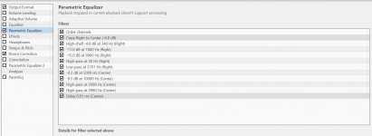
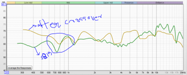
I tried to implement the DSP crossover in JRIVER software and used my 6 channel ESI U86XT soundcard for implementing it. I connected it to the current foam box where the drivers are mounted on and made it play some songs. I have attached screen shots of the crossover I designed the crossover in vituixCAD and did its implementation of it in JRIVER. The measurements used for designing the crossover are horizontal polar only ones I had taken and posted about the mid and tweeter in a previous post. I attached pics of above details below. One thing I understood from this exercise is it is really a hassle for a beginner with software dsp crossover. 😀
compared to the plug and play approach of MiniDSP etc. But eventually I made it work somehow.
I also think I have some clue about the weirdness around 1 kHz. Thought I got some clues from measurements and graphs here which Juhazi had given me earlier. chamfering driver holes
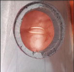
It could be due to the llack of a sufficiently deep chamfer around the back of the mid on my foam baffle. the baffle depth is about 55mm. I attached a pic below about this.
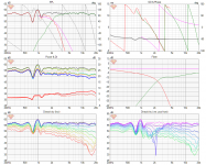
I now made a generous chamfer at the back of the mid now and tried to take a basic on axis frequency response measurement of the full prototype speaker (except the woofer) as described above with the DSP crossover in place. The chamfer issue seems to have reduced but I see all sorts of weirdness in the response especially at higher frequencies... 😀 I have attached pics of it below. I just didnt bother debugging it since the prototype box itself could be faulty and the crossover implementation could also be the issue with whatever measurements I have. Somehow I could hear it sing well though 😀 even with all the weird measurements. However one thing I noticed straight away is a kind of disconnected sound in some sings when I was very close to the speaker. About 2m+ away from the speaker, all was sounding fine to me. Could be due to the vertical spacing between mid and tweeter I think
I think this current prototype box has reached the end of its life. From now on I will probably work only on a real final box for measurements. Seems like I really have a long long way to go and need to learn a lot more 😀
Attachments

Last edited:
I went and took a look at the specs of the Wavecor WF120BD03 at hificompass website and it seems to really have some good features like really good normalized off axis directivity, lower inductance, lower linear excursion specs for a midrange purpose (hence hopefully less rubber in the surround), lower cabinet volume requirement, lower driver diameter compared to the Sb15NBAC driver (probably CAC driver has very similar specs) .. 😀 Where the NBAC slightly has an advantage is the 5dB ish lower odd harmonic distortion specs.. But it is already at very low levels we are comparing against I think. Looks like a really cute driver and makes we want to buy it even if not for this project specifically. 😀
Last edited:
- Home
- Loudspeakers
- Multi-Way
- A 3 way design study