Vertex
Hey Irvynejay,does your vertex working good??
I saw you have wrong direction on tr bc series on diff stage....
Regards
black step driver of m10 / k10 is base on h900 of apex
Hey Irvynejay,does your vertex working good??
I saw you have wrong direction on tr bc series on diff stage....
Regards
OT<
vertex are fine until now still waiting to be pack hehehe
Ow...good job...
But I mean the first pcb you upload that use orange elco...
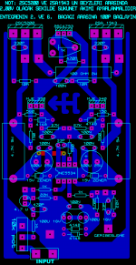
ah ok i was using different king of transistor at that time that's why it is on opposite direction
2n3906 /04
2n3906 /04
Sir apex, it is ok to replace optoresistor NSL32 with optotransistor? If ok , please show me the schematic.
Hi all DIYers!
I have the B500 built, it's just about to test. I also plan to build the H900.
A few question about this two amps:
-I have some VTL5C1 lying around, can it be used in the limiter with 47k parallel on resistor side?
-I also have a bunch of MJW21195-MJW21196 pairs, would be they ok instead of 5200-1943?
And one more thing, I want to use the H900 for bass guitar on 4 ohm load. It would be safe enough on low frequencies?
Thanks for any advice, keep up the nice work!
I belive your Motorolas (ONSEMI) are much BETTER than the 5200/1943 , especially in a PA / Heavy Duty application.Hi all DIYers!
-I also have a bunch of MJW21195-MJW21196 pairs, would be they ok instead of 5200-1943?
Have a look on SOA curves....
Thats good to hear, I didn't actually check the datasheet.
I have 14 pairs of MJW's, my goal is 1500W on 4 ohms.
Would be that possible with one channel of H900? Or easier
with a bridged B500? I don't want to bridge if not necessary...
I have 14 pairs of MJW's, my goal is 1500W on 4 ohms.
Would be that possible with one channel of H900? Or easier
with a bridged B500? I don't want to bridge if not necessary...
Counterfeit and Genuine.
why mosfer needs to matching and pls tell me the prosedure.
and can genune part needs the process of matching.
pls sir apex reply..🙂
What is the power output of H900 in 4r / 8r?
8 ohms - 500watts
4 ohms - 900watts
but will be more if you use higher power supply and higher power trannies
Last edited:
hi apex sir,
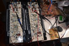
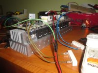
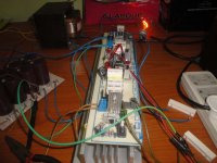
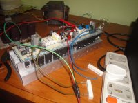
here is h900.
supply dc votage is 100-50-0-50-100. sound is excellent.
one question , without load i increase the volume ,and i see the clipping led is blink, but i checked the out with dmm ,ac voltage is 26vac. is there any mistakes from me.
thanks.
one question for tony, can u tell me what is the exact ampere of this transformer.
40 into 4 transformer,
core size is 40mm by 79mm.
thanks
Attachments
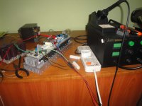
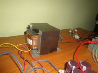
Tell me the values of A and H of the transformer power you have (see the picture below).hi apex sir,
.... can u tell me what is the exact ampere of this transformer.
40 into 4 transformer,
core size is 40mm by 79mm.
thanks
Attachments

Tell me the values of A and H of the transformer power you have (see the picture below).
hi donpetru,
A-4.5 inch,
H-3 inch,
thanks.
STEP 1:
A = 4.5 inch = 11.43 cm;
H = 3 inch = 7.62 cm.
STEP 2:
Then calculate the coefficient a = A / 6 = 1.9 cm.
STEP 3:
After step 2 is calculated active section of the core:
- first: b = 2 *a = 3,8 cm;
- second: S = b * H = 3,8 * 7.62 = 28.95 cmp (square centimeters).
STEP 4:
Now calculate the apparent power of the transformer (primary winding):
P1 = S * S = 28.95*28.95 = ~850VA.
Efficiency of such a transformer is about e=85%. In this case secondary power will be:
P2 = P1*(e/100) = 0.85*850 = 722.5VA.
STEP 5:
Knowing secondary electrical transformer voltages we can determine secondary winding current value using the following formula:
I2 = P2 / U2.
For example, you have two DC voltage of 100V (filtered with capacitors). Now, I refer to a symmetrical voltage of + / - 100Vdc, this means 200Vdc. The secondary voltage will be effective:
Vs = 0.707 * 200 = 141.4 VAC.
In this example, the secondary winding current will be maximum:
Is = P2 / Vs = 5.1 A.
So, if those 141.4 VAC are given by two voltages of about 70V each then current calculated above will be given by each winding.
I hope you understand me and I hope I was helpful.
hi donpetru,
A-4.5 inch,
H-3 inch,
thanks.
take note that calculations are at best estimates, since the quality of your irons are unknown....
From RDH4 i estimate your iron as capable of 630 volt-amperes, not far off from donpetru's calculations....
heat is a single biggest determinant to how much power you can draw out of your power traffo...... the less power you draw out, the lower the temperature...
if your traffo is M6, then you can draw more...losses with this kind of iron are lower...
Last edited:
- Home
- Amplifiers
- Solid State
- 900W H-class PA Amp with Limiter