Class AB or just a general cleaning up?
nothing magic
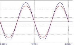
the clipping is caused by positive grid.
On the secondary even harms. are cancelled.
furthermore high harm are attenuated by freq. response
of trafo.
my simulation gives similar results:
Attachments
How did you pick the 20Vrms,
my mistake.
read:
"Reading at (o) has to be 100 Vrms while, naturally in (o1) (B config.) you will read 200 Vrms."
Is intended for duplicating real condition on the trafo.
yuo need a 200Vrms supply.
Federico
no magic?
Hi Federico,
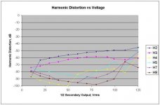
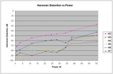
Nothing magic? It seemed pretty interesting to me when I had just measured the THD on the secondary side at 0.78% and then saw that rimary side waveform. I guess a good argument for transformer coupling if you plan to overdrive your amp? I will attach the graph of output measurements. Ignore any value less than -80dB, except for the first datapoint. The values are just placeholders used to keep excel happy when the distortion for the order was below detection limits.
Any suggestions for other drivers that give performance like this and support A2 operation? That is, assuming it is not the transformer saturation. It will take me a while to rig a supply for 200Vrms to test the transformer, but I will figure it out and do it sometime this morning.
Michael
Hi Federico,
Nothing magic? It seemed pretty interesting to me when I had just measured the THD on the secondary side at 0.78% and then saw that rimary side waveform. I guess a good argument for transformer coupling if you plan to overdrive your amp? I will attach the graph of output measurements. Ignore any value less than -80dB, except for the first datapoint. The values are just placeholders used to keep excel happy when the distortion for the order was below detection limits.
Any suggestions for other drivers that give performance like this and support A2 operation? That is, assuming it is not the transformer saturation. It will take me a while to rig a supply for 200Vrms to test the transformer, but I will figure it out and do it sometime this morning.
Michael
Attachments
1660 60Hz test
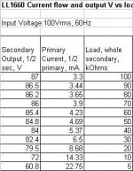
I tested the 1660 at 100Vrms and 60Hz input. I must say first, I had a particularly ugly sine wave coming out of my variac today. I used the setup in Federico's first schematic only with 60k from each side of the primary to the CT. All CT were connected together, ie isolation transformer, secondary and primary of the 1660 and grounded to the line through the ground connection of the scope. When I overlaid the waves from the primary and the secondary and decreased the load on the secondary, the amplitude of the secondary wave decreased some, but the waveform stayed identical. I varied the load from 100k to 4k. The current in 1/2 the primary ranged from ~1 mA to ~5.5 mA. Anything in particular I should be looking for? Or is it the amount of amplitude change?
Michael
hi Michael
great effort, I see.
so, the trafo does not saturate as you have
correctly predicted.
The amplitude decrease is caused , I think, from
combined supply and trafo internal res. Current has to increase with low res.
I continue to be confuded about the reason(s) of bad
performance of the amp in class A2.
Would be great if you can post a table
with 3 columns. at 100Vrms, from 5k to 100k
load, say 10 steps:
1)load
2)amplitude
3)primary current
Hi federico
Amplitude loss seems rather higher than I thought.
Just a little
HI,
probably you have some res in the generator or the trafo
has a DC res a bit higher than declared.
To me, it seems the trafo is ok.
What about try to drive the 845 with that generator to see
what happens (to distortion) when grids become positive?
If nothing happens then, definitely, it is the driver that has to be changed since you need something with lower internal res.
On the other hand, if distortion become higher when grid is
positive then you are in trouble since it means that also the res
of the trafo is critical.
Your solution surely works but it seems to me not very cheap.
Before we can try other ways.
Federico
60Hz test
Hi Federico,
You mean try to drive the 845 grids with an isolation transformer straight from the wall outlet? First, if I were to try that, you are sure I wouldn't damage the LL1620 with the high amplitude 60Hz signal? It takes rather some time to measure the distortion, so it would have to run for a few minutes to do a test. Also, my distortion measurements at 60Hz are not so accurate, because of less accuracy in the HP302A, I think, and also because of all of the line and hum harmonic interferences.
Over the weekend I tested the amp with higher voltage on the 845 plates. I used 854V plate, -123V grid, 0.5V cathode, 78mA plate current, ceteris paribus.
With input of 1.16Vrms input I measured 1.19 and 1.20 Vrms on the two secondaries of the LL1676, 16.55 and 16.18Vrms on the grids of the 12B4, ~250V pk-k on the secondary of the LL1660 and 16.5Vrms output from the LL1620 with an 8 ohm load. Here is the graph of output distortion for the series of measurements. Third order is rather higher than I hoped. Does anything seem to jump out as not right?
Michael
Attachments
You mean try to drive the 845 grids with an isolation transformer straight from the wall outlet? First, if I were to try that, you are sure I wouldn't damage the LL1620 with the high amplitude 60Hz signal?
Hi Michael
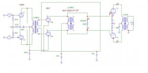
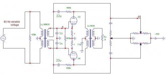
I mean something like the following pic.
With your variable generator at about 210Vrms
you should obtain a Vp-p of 250V in (a), that is at the grid
of 845, with 40V grid positive and about 40W.
ciao
Federico
Attachments
Michael
Do you remember the tale in post #130?
There are methods to decrease distortion due to abrupt change in load res due to grid current. One of the more simple is by
SAFAR (1950’s).
If I have a stage that perform well both at high and low load but, owing to the high internal resistance, distorts very much if the load is step varying then I have to make the load constant.
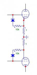
This can be accomplished by using a diode and a resistance in serie between grid and cathode as
In the pic. When grid is positive current flows only in the grid because of the diode. When grid
Is negative current flows in the diode.
The right value of resistance is found by dividing positive grid Voltage by associated peak current,
For instance: 40V/4ma= 10k.
In this way the drive always sees a load (quasi) constant of 10k.
This method is usually applied with automatic bias since the resistance (10k) need a non small current. In your case there will be a static current of 85/10k = 8.5 mA. So the C- supply has to be able to deliver such a current.
Federico
Do you remember the tale in post #130?
There are methods to decrease distortion due to abrupt change in load res due to grid current. One of the more simple is by
SAFAR (1950’s).
If I have a stage that perform well both at high and low load but, owing to the high internal resistance, distorts very much if the load is step varying then I have to make the load constant.
This can be accomplished by using a diode and a resistance in serie between grid and cathode as
In the pic. When grid is positive current flows only in the grid because of the diode. When grid
Is negative current flows in the diode.
The right value of resistance is found by dividing positive grid Voltage by associated peak current,
For instance: 40V/4ma= 10k.
In this way the drive always sees a load (quasi) constant of 10k.
This method is usually applied with automatic bias since the resistance (10k) need a non small current. In your case there will be a static current of 85/10k = 8.5 mA. So the C- supply has to be able to deliver such a current.
Federico
Attachments
clamp
Hi Federico,
I am interested to see the results of the two circuit tests you propose, so I will try to do them today. I am slightly familiar with the diode being used as a grid clamping circuit and I think with some rearrangements my C- shoud be able to supply the current.
This question though, in the end will the results of low B+ and A2 operation offer superior results to higher B+ and A1 limit, or is it more in the category of interesting design problem?
Michael
This question though, in the end will the results of low B+ and A2 operation offer superior results to higher B+ and A1 limit, or is it more in the category of interesting design problem?
I have not understand well your sentence , however I
think the best would be high B+ AND A2 operation.
Federico
diode
Tried the diode-10k from grid to ground and it didn't appear to have any effect, negative or positive. Except that the C- had to put out quite a few milliamps.
Suggestions?
Michael
Tried the diode-10k from grid to ground and it didn't appear to have any effect, negative or positive. Except that the C- had to put out quite a few milliamps.
Suggestions?
Michael
Hi
10k was an example.
Only you can measure peak current when grid is positive and
calculate suitable resistance.
I advice a 20k pot .
Federico
10k was an example.
Only you can measure peak current when grid is positive and
calculate suitable resistance.
I advice a 20k pot .
Federico
Here is the graph of output distortion for the series of measurements. Third order is rather higher than I hoped
I see about 38W at 1% dist. and 52W at 3%.
not so bad!
Federico
diode resistor
Hi,
Federico, I suspect 10k was about right based on your 4mA estimate of current. That seems about what I measured a while back. I don't think my power supply could drive anything lower than that. I was quite surprised that it appeared to have no effect either way, unless I had something hooked up wrong. Seemed pretty straightforward though. I guess second harmonic was a bit higher, I usually don't pay too much attention to it since it seems to be quite adjustable.
I did a test yesterday with 850V B+ and -125V bias with 98Vrms signal on the secondary of the 1660 followed by the same test at 650V B+ and -86V bias with a 74Vrms signal. These should be close to the same amount positive from the grid bias voltage. The distortion levels were very similar, all that varied was the output achieved.
Michael
hi
speaking about how decreasing the influence of positive
grid.
If you translate the static loadline toward higher currents the
grid current decreases.
With the same positive grid voltage, say 40V, you will
have lesser grid current.
what you think about 90mA?
Federico
speaking about how decreasing the influence of positive
grid.
If you translate the static loadline toward higher currents the
grid current decreases.
With the same positive grid voltage, say 40V, you will
have lesser grid current.
what you think about 90mA?
Federico
- Status
- Not open for further replies.
- Home
- Amplifiers
- Tubes / Valves
- 845 PP and Lundahl 1620