I think you want the plates going red hot in this tube.. It has to do with the getter action.
See here:
http://www.diyaudio.com/forums/tubes-valves/24424-where-833-amps-6.html#post350083
See here:
http://www.diyaudio.com/forums/tubes-valves/24424-where-833-amps-6.html#post350083
Last edited by a moderator:
Yes, I understand the True Operating Condition of the 833 tube is red hot plate for use as Transmitter. I saw that post and asked myself the same question.
How can a Red Hot Plate can sound good for Audio? Would red hot plate the distortion lower or higher? I guess I would never know till I try and build one.
How can a Red Hot Plate can sound good for Audio? Would red hot plate the distortion lower or higher? I guess I would never know till I try and build one.
I think it's potentially important though (sound aside) because it is responsible for the getter action.. In that it is removing gas from the vacuum.. ? If you didn't run the plate red hot the tube could become gassy.
I don't know about the working details of the 833. But usually the heater provides the required temperature for the getter actions and not the red hot plate.
PT hum from professional transformers 2X 600VAC 400watts, very cheaps but noise.I do indeed hear a low hum with a 2500V Hammond 733A transformer into a full wave bridge. I had a cover made for it and lined it with Soundcoat sheets and I can't hear it from the listening position, and barely from 3 feet away.
One of these days I'll take the PTs off and have them vacuum impregnated, but I'm in no rush.
laminations side soldered no screwed, in my GM70PP its good idea potting and encapsulating compound ?
.http://docs-europe.electrocomponents.com/webdocs/0d3e/0900766b80d3e10f.pdf
anyone try this way ?
With any Hi Mu triode you need well damped speakers or the amp needs lots of feedback.
I have not built amps using 833's but have built 805 S Ended, PP 805, PP8000, PP 811a's, PP 810's. If you use well damped drivers like Altec 515's, JBL 2020's, Etone, 805's 475's; and lots more; 12bd feed back is plenty, most modern speakers will be boomy; Used with these tubes. Without feedback the internal impedance can be as high as 10ohms or more. According to the Japanese the 833 works very well at 1000 volts.
Phil
I don't know about the working details of the 833. But usually the heater provides the required temperature for the getter actions and not the red hot plate.
Barium based getters ('silver flash') work at much lower temperatures than the zirconium getter used in the 833a.
Barium sits on the glass (250 Celsius max), where zirconium is applied directly to the anode. To get to the required 1000 Celsius, the anode needs to be red hot 😎
But usually the heater provides the required temperature for the getter actions and not the red hot plate.
This is true with most small receiving tubes. Their getter is usually a barium oxide compound that is deposited on the glass surface during manufacturing. These tubes should be run below the red plate region to avoid becoming gassy. Higher temperatures will cause impurities in the metal and the mica to be released into the tube, "outgassing." This causes distortion, grid current, and eventual tube runaway.
The 833A and most higher power transmitting tubes are designed differently. The plate of the tube is made from, or coated with, a material that provides gettering action. The plate must be operated at its specified temperature to provide getter action.
Some tubes, including many 833A's have both kinds of getters, with the barium oxide coating down near the bottom of the tube where it is cooler. In one of my early experiments I tried running the 833A upside down so that the high voltage would be below the chassis. The silver getter compound vanished within a few days of testing. The tube continued to work fine though.
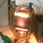
The 833A will show some plate color when operated as low as half it's rated dissipation, and glows quite brightly in normal use. It is important to keep the glass temperature down at the top of the tube to avoid failing the plate and grid metal to glass seals. This is why you see the fan at the top blowing down and heatsinks on the pins, instead of the usual glass chimney.
Whether the plate is glowing or not, has no effect on the distortion. This is true on all tubes, large and small, however a glowing plate in a receiving tube WILL contaminate it's vacuum, and that will raise the distortion among other things.
The Rp of the tube decreases with current, so a higher plate current can improve damping factor.
.
In one of my early experiments I tried running the 833A upside down so that the high voltage would be below the chassis. The silver getter compound vanished within a few days of testing. The tube continued to work fine though.
The Rp of the tube decreases with current, so a higher plate current can improve damping factor.
Two things I was wondering about.. So thanks for that info
It would probably work, but the maximum rated continuous plate current is 500 mA. The maximum rated continuous rated continuous plate dissipation for the old style (not graphite plate) 833A is 400 watts, this puts the plate voltage at 800 volts to be capable of reaching the maximum ratings.
I learned a lot of my tube electronics from some older ham radio guys in the 60's, when they actually built big RF amps with transmitting tubes. They always said to get the most tube life, use the highest possible voltage and the least possible current to get the power you need. This is a bit easer with RF since changing the load impedance is usually only a knob twist, or maybe a coil tap change away. They stated that cathode current is what wears out the filament / cathode, and I believe I saw that statement in some Eimac literature a zillion years ago as well.
That said, I have some 833A's and some Hammond 1628SEA's which are nowhere near capable of eating kilovolts, so there is a happy medium somewhere, but I don't have time to go looking for it in the near future. I'm guessing, maybe 800 to 900 volts.
For anything below about 700 volts, the best performance can be had with TV sweep tubes. If I wanted to go DHT on 700 volts less, I would use a 211, 845 or triode wire an 813 or two or three.
"or triode wire an 813 or two or three."
We'll know it's going to be a cold winter when George starts on that one.
We'll know it's going to be a cold winter when George starts on that one.
Last edited:
This is true with most small receiving tubes. Their getter is usually a barium oxide compound that is deposited on the glass surface during manufacturing. These tubes should be run below the red plate region to avoid becoming gassy. Higher temperatures will cause impurities in the metal and the mica to be released into the tube, "outgassing." This causes distortion, grid current, and eventual tube runaway.
The 833A and most higher power transmitting tubes are designed differently. The plate of the tube is made from, or coated with, a material that provides gettering action. The plate must be operated at its specified temperature to provide getter action.
Some tubes, including many 833A's have both kinds of getters, with the barium oxide coating down near the bottom of the tube where it is cooler. In one of my early experiments I tried running the 833A upside down so that the high voltage would be below the chassis. The silver getter compound vanished within a few days of testing. The tube continued to work fine though.
The 833A will show some plate color when operated as low as half it's rated dissipation, and glows quite brightly in normal use. It is important to keep the glass temperature down at the top of the tube to avoid failing the plate and grid metal to glass seals. This is why you see the fan at the top blowing down and heatsinks on the pins, instead of the usual glass chimney.
Whether the plate is glowing or not, has no effect on the distortion. This is true on all tubes, large and small, however a glowing plate in a receiving tube WILL contaminate it's vacuum, and that will raise the distortion among other things.
The Rp of the tube decreases with current, so a higher plate current can improve damping factor.
Thanks! You explained it pretty well about the proper getter requirement for the 833A.
I am only thinking to put the 833A in upright position when I have devised my own sockets for the tube.
Is conventional cooling sufficient or better with forced air cooling for the longevity of the tube life?
I am looking to run my 833 at 800V-1200V and 0.25A supply. It'll give more than enough power that my OPT can handle which is 40W.
Last edited:
We'll know it's going to be a cold winter when George starts on that one.
This basement needs some warmth. It hit 45 degrees F in here several times last winter, which wasn't as cold as the winter before.
One 833A consumes 100 watts just to light the filament....that's equal to the maximum plate dissipation of the other tubes I mentioned, 211, 845, and 813.
I sold all my 813's and many of my 833A's several hamfests ago. I still have several 833A in a box somewhere.
Is conventional cooling sufficient or better with forced air cooling for the longevity of the tube life?
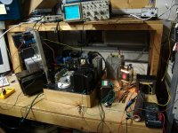
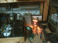
The guts inside an 833A can take some heat. The metal to glass seals at the pins are the weak point. I would advise some airflow. It wouldn't hurt the tube, but everything around the tube will get hot from the IR those guys put out. You can feel it from several feet away. Of course I was running mine pretty hard, 1500 volts and 275 mA.
Note that this was a breadboard test amp cobbled together from a Motorola power supply from an old tube transmitter (1500V, 500 mA), my 845SE amp, a 10 volt transformer with 4 X 10 amp windings, a custom OPT, a small bench power supply, and a big cap from an old cardiac defibrillator. It existed for about a week and for all but a few pictures there was a thick Lexan shield between me and the amp. Extremely lethal voltage with Vise Grip, hose clamp, and Radio Shack clip lead construction is definitely not a safe environment.
Attachments
why not try 500v at higher current with 833?
It would probably work, but the maximum rated continuous plate current is 500 mA. The maximum rated continuous rated continuous plate dissipation for the old style (not graphite plate) 833A is 400 watts, this puts the plate voltage at 800 volts to be capable of reaching the maximum ratings.
Maybe something like this?
~1K output transformer (1.1 * 950V)
Biased at +50V, putting the tube at 500V / 500mA
Pd ~ 250W (I wonder if that would get the plate hot enough?)
I wonder how this would sound?.. Would be neat to try since you could get away with an easy power supply. Though I don't imagine 1K / 500 mA output transformers are overly easy to come by..

 you must push it hard into "darlington" mode
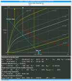
Maybe something like this?
~1K output transformer (1.1 * 950V)
Biased at +50V, putting the tube at 500V / 500mA
Pd ~ 250W (I wonder if that would get the plate hot enough?)
I wonder how this would sound?.. Would be neat to try since you could get away with an easy power supply. Though I don't imagine 1K / 500 mA output transformers are overly easy to come by..
1K/500mA=2000ohms Rp
Rl would have to be much higher around 4K or more.
10K Transformer should work the same.
I know you have asked about damping factor. In my experience, the overall damping factor is really a big factor at the low bass. You'll need a really good OPT with high enough L for the bass to shine.
Like many Japanese design, one reason to use IT to drive the output tube (to delivery the immediate sense of deep bass) for that low Frequency response with so-so OPT transformer with not very high L.
The guts inside an 833A can take some heat. The metal to glass seals at the pins are the weak point. I would advise some airflow. It wouldn't hurt the tube, but everything around the tube will get hot from the IR those guys put out. You can feel it from several feet away. Of course I was running mine pretty hard, 1500 volts and 275 mA.
Note that this was a breadboard test amp cobbled together from a Motorola power supply from an old tube transmitter (1500V, 500 mA), my 845SE amp, a 10 volt transformer with 4 X 10 amp windings, a custom OPT, a small bench power supply, and a big cap from an old cardiac defibrillator. It existed for about a week and for all but a few pictures there was a thick Lexan shield between me and the amp. Extremely lethal voltage with Vise Grip, hose clamp, and Radio Shack clip lead construction is definitely not a safe environment.
I saw that vise grip holding the tube and I would be scared to come near you. I have a few 10V 17A transformer for the filament duty.
Where do you get your Custom OPT?
Nothing about this project is cheap and budget friendly!

I think the old Radio and Telecom Engineers would be rolling in the grave seeing that we are planning SE for the tubes intended for Class B or C at RF.
I was looking at that Hammond a year or so ago and George saved me from spending my money. He found a resonant peak on that transformer.
The spec looks good (FR, power handling; etc.) for a BIG SE transformer. The thing is huge and 28lbs so I was impressed. The question is 53H at what frequency?
I have also seen some other people with Hammond SE OPT realized a similar problem with what George said. It would still be a good and very usable transformer depends on where you used it though.
- Status
- Not open for further replies.
- Home
- Amplifiers
- Tubes / Valves
- 833A "budget" design