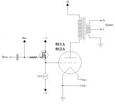
Ok, I've finally gotten around to looking into upgrading my current home amp. Right now I have a 6146SE (6C4 driver) and plan to move/swap/upgrade to some 812As driven by 6SN7s. Here's the circuit I'm going to use.
I've already scratch-built it and it sounds great (Fostex 166ENs in a BIB)
I've already scratch-built it and it sounds great (Fostex 166ENs in a BIB)
An externally hosted image should be here but it was not working when we last tested it.
Last edited:
Here's a shot during last night's tweaking. Here she was pulling about 125mA.
"She's running hot old man...reeeal hot" - my favorite line from the film "Used Cars"
"She's running hot old man...reeeal hot" - my favorite line from the film "Used Cars"
An externally hosted image should be here but it was not working when we last tested it.
The scratch-built circuit. 80.7mA plate current.
I build on these copper-clad boards that I would take from trash cans when I worked for a defense contractor.
The power transformer I'm going to use is from a Kenwood TS-520. Nice nice. Its been running for a few hours and the core is barely warm.
I build on these copper-clad boards that I would take from trash cans when I worked for a defense contractor.
An externally hosted image should be here but it was not working when we last tested it.
The power transformer I'm going to use is from a Kenwood TS-520. Nice nice. Its been running for a few hours and the core is barely warm.
Ok, here we go. I get a couple of the copper-clad boards and all the other goodies together and get ready to drill the holes and start mounting parts.
I build each channel, and the power supply board, all as modules.
An externally hosted image should be here but it was not working when we last tested it.
I build each channel, and the power supply board, all as modules.
Ok, I've finally gotten around to looking into upgrading my current home amp. Right now I have a 6146SE (6C4 driver) and plan to move/swap/upgrade to some 812As driven by 6SN7s. Here's the circuit I'm going to use.
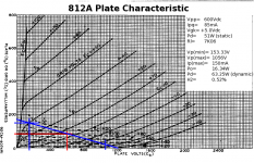
I once thought about doing a SET with 812's, but couldn't locate a decent OPT. Based on that preliminary design, there seems to be something funky about that schemo. Zero bias and capacitor coupled? You can bias an RF amp like that, but it doesn't work for audio.
How do you get enough plate current without positive grid bias? I had to have Vgk= +5Vdc to pull the necessary Q-Point bias. (Loadline, attached) It is, after all, a rather high-u VT, even if not nearly so high-u as the similarly rated 811A.
Attachments
Miles,
Maybe I am looking at this wrong or most likely missing something, but with 800V B+ and considering losses in OPT, Cathode resistor, and error in manufacturing, it looks to be reasonable to have 0V grid for 80 mV of plate current
Maybe I am looking at this wrong or most likely missing something, but with 800V B+ and considering losses in OPT, Cathode resistor, and error in manufacturing, it looks to be reasonable to have 0V grid for 80 mV of plate current
With zero bias, or even a little negative bias that driver circuit isn't gonna cut it. The 812A starts to draw grid current at around -5V. Cap coupling is a recipe for disaster. Add a FET follower and it would be fine.
Last edited:
G'morn. Thanks for the comments. To be truthful, I don't know why this thing is working as well as it is! I was looking into biasing the grid and the darn thing is playing very well and is stable between different tubes (both in the drive and final stages).
I think I ran it about four hours yesterday with various types of music (that we listen to) and I'm amazed at how well it sounds and that was using a power transformer (Pri 125V / Sec 16V) that I nabbed from a bad UPS power supply as the OPT! Like I said, it is scratch-built right now. I measured the impedance of that thing once and it was around 1600 ohms @ 1kHz. Inefficient as heck though. haha
I like the idea of the FET follower in case of disaster.
I've never worked with an 812A before. It seems a bit temperamental compared to its cousin the 811A.
One thing, as the cathode rises above ground, then the grid goes sinking below ground.
This config is putting in the neighborhood of -5V on the grid. The plate is barely glowing with no room lights on and it sounds really sweet.
This config is putting in the neighborhood of -5V on the grid. The plate is barely glowing with no room lights on and it sounds really sweet.
Hi 812a,
Take a look at sine curve, when going into A2 with C coupling. Not a nice sine curve any longer, heavy cut and lots of THD !
Use FET, 2sk2700, source follower or a cathode follower, 6hv5, DC connected of cause.
Best regards
Karsten
Take a look at sine curve, when going into A2 with C coupling. Not a nice sine curve any longer, heavy cut and lots of THD !
Use FET, 2sk2700, source follower or a cathode follower, 6hv5, DC connected of cause.
Best regards
Karsten
One thing, as the cathode rises above ground, then the grid goes sinking below ground.
This config is putting in the neighborhood of -5V on the grid. The plate is barely glowing with no room lights on and it sounds really sweet.
But you are basically wasting more than 90 VA to get 0.5-1W in the best case?? Try to crank up the volume and see what happens....
But you are basically wasting more than 90 VA to get 0.5-1W in the best case?? Try to crank up the volume and see what happens....
Yes, it does get a tad nasty when driven hard. 🙂
I'm gonna add the C follower to the dummy test and see how it does.
I saw another circuit on here for an 811A that was basically a 6SN7, into a 6V6 (CF), then into the 811A. I may look into that config as well.
Here it is
Last edited:
Yes, it does get a tad nasty when driven hard. 🙂
I'm gonna add the C follower to the dummy test and see how it does.
I saw another circuit on here for an 811A that was basically a 6SN7, into a 6V6 (CF), then into the 811A. I may look into that config as well.
Here it is
You have to look at the plate curves first. The 811A and 812A bias up at different points. Just use a FET follower and you will be able to drive the grid anywhere you want it.
Attachments
Thanks for all the help. I plan to revisit the project this weekend. Our forecast is rain (again).
Modified circuit 1.
This has less parts, but generates a tad of heat there in the cathode resistor of the 812A. The circuit sounds nice and clean from no volume to full volume.
--
This has less parts, but generates a tad of heat there in the cathode resistor of the 812A. The circuit sounds nice and clean from no volume to full volume.
--
An externally hosted image should be here but it was not working when we last tested it.
Modified circuit 2.
More parts, less heat. I'm gonna build this one. I'm running about 60 mils of plate current here.
More parts, less heat. I'm gonna build this one. I'm running about 60 mils of plate current here.
An externally hosted image should be here but it was not working when we last tested it.
Last edited:
I have made several 812 PP amps using 6BL7 as cathode followers, but at 600 volts and 70 ma, With negative bias. I would have thought 800 volts 90ma was too high no wonder they go red.
Phil
Phil
I have made several 812 PP amps using 6BL7 as cathode followers, but at 600 volts and 70 ma, With negative bias. I would have thought 800 volts 90ma was too high no wonder they go red.
Phil
Ha! yep. They are much happier now - loafing along at about 60 mils.
- Status
- Not open for further replies.
- Home
- Amplifiers
- Tubes / Valves
- 812A Build