PP 809's can sound quite good. As stated earlier this isn't a true class B operation because the tubes do run a significant idle plate current. But, class B is what we called it. The trick using them is a low impedance driver and stable bias voltage. When the grids draw current they can raise the grid voltage in a poorly designed bias supply.
In the old AM transmitter days they were typically driven by PP 6B4 or triode connected 6V6's transformer coupled to the grids of the 809's. A quality transformer, grid swamping resistors, and zener regulated bias helped minimized distortion. The distortion that was present was low order and not very offensive usually. The presence of both a driver and output transformer in such an amplifier introduced too much phase shift to make global feedback practical.
If you want to use global feedback your circuit needs to eliminate the driver transformer. Gates did this in some of there broadcast transmitters utilizing class B 833A's by driving the output tube grids directly with cathode follower's. I'm sure you cold use solid state devices too. However this is getting away from old school tube technology.
Hope this is helpful.
As stated earlier this isn't a true class B operation because the tubes do run a significant idle plate current.
I see that this is a real B-class operation. The 20 mA idle current is only one fifth of the anode current at full power.
20 mA idle current could be significant in case of EL84 and similar size of tubes, but not in output tube of 100 W amplifier. Actually this (20 mA) corresponds some 4 mA idle current in EL84. I do not also see that this 4mA is significat at all.
Class B operation has been determined - at least on tube circuits - such a state when tubes are biased to almost - but not completely - to the point of plate current cut off.
Then why it is not a class AB2 ?
The difference between class AB1 and AB2-operation is on driving level, not (typically) between bias.
One can easily see that a pair of 809 triodes biased for 2 x 20 mA idle current has -9 V grid voltage. So the max. driving voltage for AB1 class operation could only be 18 Vpp (compared to 155Vpp at class B) .
In this case the output power would be just few watts. So this bias arrangement (Ug = -9V, Ia = 20 mA) can not represent AB-class operation.
Yes.
They're not. The pic is of the result of subtracting the input from the output with an op-amp linear subtractor. What's left is the difference (i.e. distortion). It's not a complete null due to phase shift at the test frequency (166Hz). The "little fuzzies" are the result of one side of the PP pair handing off to the other side, as one final goes into plate current cutoff. If you aren't using a linear subtractor, you can't see anything by o'scoping either the primary or secondary, and there are definitely no RF parasitics. ("Snivets" are quite obvious.)
This occurring with 6BQ6s biased to Ip= ~50mA (biased hot: ~17.5W of static Pd -- spec busting as Pd(max)= 12W according to the spec sheet. Since these were originally designed as HD finals, the ratings are very conservative, and so spec busting for audio final operation does no harm.)
I observe the same.
I have a breadboard with a high leakage OPT, on which I can twiddle the bias settings and move the turnoff glitch nearly up to the peak of the sine wave. It doesn't take much overlap because my driver is trying to stretch out the turn-off. In doing so, it simply moves the glitch around, but doesn''t eliminate it.
I'm convinced that there needs to be cross-coupled differential feedback or someting to control the turning-on side to completely eliminate this.
Michael
The differential feedback might be of some help for limiting the glitching by smoothing the transition of current, but I think one is still faced with the fundamental problem here that the turning off tube has no transconductance left at low currents. So any feedback is loosing control at the final cut-off. Perhaps one could limit the grid signals to the tubes such that they never quite turn off, a diode limiter for each tube grid of some kind maybe.
Makes me think of the Carver 6AL5 diodes scheme. The grid gets softly limited from swinging more neg. than 2X bias V. Not so convenient for a power output tube though unless a separate neg. 2X bias supply is available.
http://www.diyaudio.com/forums/tubes-valves/135052-what-if-o-h-schade-had-mosfets-2.html#post1689375
Last edited:
"remote cut-off output tubes"
Aren't those usually about 2 Watts? Unless you've got hundreds of them to parallel.
Kenpeters mentioned fixing crossover dist. with some Schottky diodes strung in series under the tube cathodes. Whether that would help for the glitch problem too I don't know.
Aren't those usually about 2 Watts? Unless you've got hundreds of them to parallel.
Kenpeters mentioned fixing crossover dist. with some Schottky diodes strung in series under the tube cathodes. Whether that would help for the glitch problem too I don't know.
Last edited:
remote cut-off output tubes
Aren't those usually about 2 Watts? Unless you've got hundreds of them to parallel.
...or make Darlingtons, with power transistors: BJTs, or MOSFETs...
...or make Darlingtons, with power transistors: BJTs, or MOSFETs...
Someone recently has put a little class A stage in parallel with the bigger switching elements. They also made the switching elements track the class A element using feedback.
It should also be possible to emulate a remote cutoff, maybe using the diode scheme etc., such that the less-conducting side never turns off completely (using only regular beam tubes).
According to the definition in RDH4, we now have a class A amp 😀
Michael
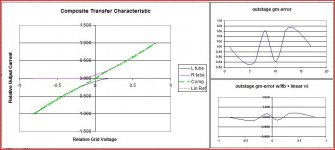
PS For me, there is not much practical difference between class AB (current flow appreciably more than 1/2 the cycle) and class B (plate current "nearly" cut off) because I find that there is a particular point in the overlap where the crossover distortion due to the combination of 2 tube curves is optimized. The attached graph shows a 3/2 power approximation to illustrate, but real valves deviate from the 3/2 power curve at low plate currents and need to be measured. To my mind, the only thing huge conduction overlap buys you is delaying the occurence of the turn-off glitch.
Attachments
Last edited:
I use class A+C approach in transistor amps starting from 1978 (77?), but did not try it with tubes though, because I am afraid of output transformers...
It should also be possible to emulate a remote cutoff, maybe using the diode scheme etc., such that the less-conducting side never turns off completely (using only regular beam tubes).
Just use 6AS7's. It is almost impossible to cut one of those things completely off. This is how some OTL's are called "class A".
Just use 6AS7's. It is almost impossible to cut one of those things completely off. This is how some OTL's are called "class A".
Huh...
Keep the off-side from going completely off by clipping/rounding off the bottom of the the drive waveform. Saves on the negative drive voltage that's not needed. Could probably use a little stiff cathode bias and avoid a negative drive supply altogether. Or g2, g2+g1 drive methods which are positive-biased. Or with a high impedance triode like the type 809.
That plus high gain local feedback e.g. to a pentode driver, might avoid the glitch. Of course, the feedback needs to go to a full swing driver, with the drive waveform negative-limited in the powerdrive section.
Time to break out the test amp again. George, those geetar OPTs are great for playing with the turnoff glitch! High leakege inductance
Michael
Last edited:
Hmmm... remote cutoff should be doable if one modulated the screen of an output pentode properly no?
Could maybe put a small CCS across each tube to set a minimum current draw. Maybe with a slow RC drop off control of the CCS so it would drop out for quiet periods.
What effect does high leakage inductance have on the glitch?
Huh...
Keep the off-side from going completely off by clipping/rounding off the bottom of the the drive waveform. Saves on the negative drive voltage that's not needed. Could probably use a little stiff cathode bias and avoid a negative drive supply altogether. Or g2, g2+g1 drive methods which are positive-biased. Or with a high impedance triode like the type 809.
That plus high gain local feedback e.g. to a pentode driver, might avoid the glitch. Of course, the feedback needs to go to a full swing driver, with the drive waveform negative-limited in the powerdrive section.
Time to break out the test amp again. George, those geetar OPTs are great for playing with the turnoff glitch! High leakege inductance
Michael
What effect does high leakage inductance have on the glitch?
OPT leakage inductance stores some energy which is released as a reverse voltage spike when the tube driving one side of the OPT stops conducting. The greater the leakage inductance (less perfect coupling to other windings) the greater the spike.
With local differential feedback there is a special side effect:
This spike (glitch) confuses the local feedback system into trying to compensate by increasing the conduction of the tube which is in the process of taking over driving. The fed-back glitch fools the turning-on tube into thinking the other tube has gone beyond turn-off and is now sinking current, causing the turning-on tube to source even more current to compensate. The result is an anti-glitch at the output. I may have some scope pics somewhere...
Michael
Last edited:
I had such a glitch that caused nice ringing on 30 KHz, couple of years ago. Ringing was of quite high Q, and started on frequencies below 100 Hz approximately; when frequency was higher it did not ring. Most probably, when driving with frequencies closer to saturation (Edcor specified 20 Hz on full 100W power), something in M6 iron caused it to increase leakage inductance.
How did I solve the problem? Tried Zobels between anodes, but I did not have 20K resistors of higher than 2W value, so gave up the idea after dozen of them had been burned.
I increased idle currents and values of grid stoppers from 100 Ohm to 1K5. Later implemented parallel feedback across output tubes, it helped as well.
Good morning,
Lots of information has been tossed around, in reality, is this a project worth pursuing? I have 4 pairs of new RCA 809's and not sure what else to do with them. And if I do build, do I transformer it or mosfet it or perhaps sell the tubes cheap and cut my losses.
Thanks,
Ray
Lots of information has been tossed around, in reality, is this a project worth pursuing? I have 4 pairs of new RCA 809's and not sure what else to do with them. And if I do build, do I transformer it or mosfet it or perhaps sell the tubes cheap and cut my losses.
Thanks,
Ray
"I had such a glitch that caused nice ringing on 30 KHz, couple of years ago. Ringing was of quite high Q, and started on frequencies below 100 Hz approximately; when frequency was higher it did not ring. Most probably, when driving with frequencies closer to saturation (Edcor specified 20 Hz on full 100W power), something in M6 iron caused it to increase leakage inductance."
The Edcor P-Ps that I have measured have very high leakage L on the outer 60% winding on one side. Did the the Zobels help before they burned out? I assume there were two of them, each from B+ to plates. You might want to measure the frequency response of each side (separately) of the primary to the loaded output too, you might be in for a surprise.
----------------------
"is this a project worth pursuing? I have 4 pairs of new RCA 809's and not sure what else to do with them. And if I do build, do I transformer it or mosfet it or perhaps sell the tubes cheap and cut my losses."
Well these tube are big enough that driving a Mosfet with them in class AB (- grid bias) would be a little silly really, mainly just for show. Going into positive grid V will require some Mosfet followers to drive the grids, high drive signals from the driver stage, and looks like an expensive HV B+ setup and OT. Curing the glitches and crossover problems is somewhat of a research project, although I'm sure they can be tamed, it's mainly a question of which way is best to proceed. Not a beginner type project in any case, will need some decent test equipment. I myself refuse to work with any Xmit tubes over 500 V B+ simply for safety reasons. Lots of cheap Sweep tubes around that will put out good power at low B+, high current.
Solving the glitch problem though is still open territory in DIY, since Mac type OTs are not abundant. And so many OTs have obvious problems with this for at least one side of the primary.
Last edited:
- Status
- Not open for further replies.
- Home
- Amplifiers
- Tubes / Valves
- 809's in Class B P-P w/feedback