Greetings,
How horribly sounding will 809's in class B push-pull be with feedback or should I be asking how hard would it be to implement feedback in a class B push-pull amp.?
Thanks,
Ray
How horribly sounding will 809's in class B push-pull be with feedback or should I be asking how hard would it be to implement feedback in a class B push-pull amp.?
Thanks,
Ray
In true class B P-P operation (40-60% efficiency), crossover distortion will be your worst enemy. You'll need a very tightly coupled output transformer of the best quality you can get. Plate current virtually stops flowing during the negative half cycle. Because of this a very stable power supply with good regulation is required as the plate current rises rapidly to a large value on the positive half cycle.
Crossover distortion can be corrected to a large extent by applying positive bias to the cathodes of the output tubes with a small resistor in series to ground. The exact amount of this positive voltage will need to be determined by experiment since 809s are low bias tubes to begin with. Perhaps a volt or two will be enough. Further reduction of crossover distortion will be helped by lots of inverse feedback in the usual manner. But the real challenge will be the output transformer. Sound quality will largely depend on it's construction. But since there are no class B high quality audio amplifiers in use that I can think of, don't expect to produce a good one. Even the McIntosh's like the MI-200 aren't true class B. They're mostly AB2
Crossover distortion can be corrected to a large extent by applying positive bias to the cathodes of the output tubes with a small resistor in series to ground. The exact amount of this positive voltage will need to be determined by experiment since 809s are low bias tubes to begin with. Perhaps a volt or two will be enough. Further reduction of crossover distortion will be helped by lots of inverse feedback in the usual manner. But the real challenge will be the output transformer. Sound quality will largely depend on it's construction. But since there are no class B high quality audio amplifiers in use that I can think of, don't expect to produce a good one. Even the McIntosh's like the MI-200 aren't true class B. They're mostly AB2
Last edited:
Greetings,
How horribly sounding will 809's in class B push-pull be with feedback or should I be asking how hard would it be to implement feedback in a class B push-pull amp.?
Pretty awful, I'd say. You have to remember that when they're talking about Class B audio, they're talking AM plate modulators, where fidelity isn't a consideration. With Class B, X-over distortion is inevitable, and it truly sounds horrible. It's not a consideration with RF amps, since these have LC tuners and/or BPFs to remove whatever harmonic distortion that produces. For PA amps and modulators, you don't care if the sound quality isn't what it should be anyway.
If you put 'em into Class AB2 instead, and use source follower grid drivers, then they'll probably sound pretty good, especially if you include NFB to take care of the otherwise higher than normal r(p).
Then, it's just a question of finding a good loadline, and experimenting.
You can probably get Jack at Electra Print to make you the OPTs. (Edcor also does designs, I believe).
If you do build it I'd love to see the measurement results. People will drop $20k on a class B theater amp without blinking... 😕
What was called Class B (-9V G1, 20 mA/tube idle, 3.7W dissipation on first grids) when 809 was designed now is called class AB2, I believe.
What was called Class B (-9V G1, 20 mA/tube idle, 3.7W dissipation on first grids) when 809 was designed now is called class AB2, I believe.
Yes! The 809 data sheet (has anyone else looked at it today?) shows "Class B" as having 40 mA zero signal plate current; that's 20mA per tube. This is today's definition of class AB. The 3W grid power is at max signal. Grid power is very small at idle.
And it's a great example of the old assumption that class B amps are driven into grid current. Notice thay don't call it "Class B2" but there is grid current.
Today we would call it class AB2 with small overlap.
Crossover distortion:
The turn-off glitch occurs whenever one side of a switching push-pull amp turns off. Even in AB, where there is overlap, there is still a turn-off glitch. The glitch does seem to be smaller if one side turns off after the other has turned on, but it's still there and is an effect of OPT leakage inductance.
Build it!
I would not worry about the definition of class B, built the 809 amp with whatever idle current and positive grid drive makes sense for your chosen load line, and tweak it from there, just like any other amp. The only thing these tubes need vs. a "regular audio triode" is provision for high plate resistance and grid current drive (MOSFETs are our friends). Treat it like a pentode and apply local feedback. It can probably sound amazing and be really pretty with the bright filament and all...
Cheers,
Michael
Last edited:
How horribly sounding will 809's in class B push-pull be with feedback or should I be asking how hard would it be to implement feedback in a class B push-pull amp.?
What output power are you aiming at ?
This tube has potential for 145 W out as PP-connected.
Quite sufficient level for most purposes.
This tube can be used ofcourse at lower supply voltages and power levels but allways it needs to be driven with power i.e. grid current.
So you need a real driver stage.
I have experimented with relatively similar triode 811A.
A 6N6P double triode as parallel connected cathode follower works fine as a driver stage with it.
Thanks for the info Michael. Would you have any schematics of circuits I could try?
Thanks,
Ray
Thanks,
Ray
Yes! The 809 data sheet (has anyone else looked at it today?) shows "Class B" as having 40 mA zero signal plate current; that's 20mA per tube. This is today's definition of class AB. The 3W grid power is at max signal. Grid power is very small at idle.
And it's a great example of the old assumption that class B amps are driven into grid current. Notice thay don't call it "Class B2" but there is grid current.
Today we would call it class AB2 with small overlap.
Crossover distortion:
The turn-off glitch occurs whenever one side of a switching push-pull amp turns off. Even in AB, where there is overlap, there is still a turn-off glitch. The glitch does seem to be smaller if one side turns off after the other has turned on, but it's still there and is an effect of OPT leakage inductance.
Build it!
I would not worry about the definition of class B, built the 809 amp with whatever idle current and positive grid drive makes sense for your chosen load line, and tweak it from there, just like any other amp. The only thing these tubes need vs. a "regular audio triode" is provision for high plate resistance and grid current drive (MOSFETs are our friends). Treat it like a pentode and apply local feedback. It can probably sound amazing and be really pretty with the bright filament and all...
Cheers,
Michael
Re: Michael
"The turn-off glitch occurs whenever one side of a switching push-pull amp turns off. Even in AB, where there is overlap, there is still a turn-off glitch. The glitch does seem to be smaller if one side turns off after the other has turned on, but it's still there and is an effect of OPT leakage inductance."
I think there may be a couple of ways to fix that leakage glitch. (other than Mac OT or Circlotron or Twin Coupled schemes) Seeing as how the leakage L causes the plate voltage to swing up wildly positive after the tube cuts off. If one added "nominal gain" (0 dB NFdbk, ie, Closed Loop gain set to match the tube's normal gain into the load) Schade plate feedback resistor(s), the tube would be held on just enough to absorb the glitch (ie, correct tube output voltage maintained). Of course a regular Schade NFdbk should work too.
Then there is "magic" Schading, which uses current sensing Schades and a differential driver to subtract them. This forces the tubes to make a smooth current handover. No abrupt cutoff is possible then. The crossover region is widened from what the bias and intrinsic tube curves overlap would normally obtain.
Last edited:
Then there is "magic" Schading, which uses current sensing Schades and a differential driver to subtract them. This forces the tubes to make a smooth current handover. No abrupt cutoff is possible then.
Do you mean local FB by current around each tube to minimize glitches, then global FB by voltage around both of them to minimize output resistance?
Thanks for the info Michael. Would you have any schematics of circuits I could try?
Thanks,
Ray
There are plenty of circuits that would work, but first I would look at the requirements.
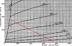
The data sheet gives some starting points; I'd look at the CCS (stands for "Continuous Commercial Service") op point load line for ~100W output. No need to push it and 100W OPTs are common in the 8K primary specified. Attached is the load line for 20mA idle, 750V.
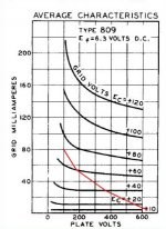
What about the drive requirement for the grid? Transposing poinits off the plate load line, the grid load is shown in red on the second curve. It looks like the grid will need 80 mA peak current. Definitely MOSFET territory, or a pretty high gm tube so as not to distort too much on peaks.
The drive voltage needed is pretty high also. I would still be tempted to use a single stage pentode driver with plate feedback from the output ala DCPP (Pete Millett amp), of course with a "power drive" like MOSFET circuit to drive the 809 grids. I'd keep the filaments at ground to make that part of the circuit easier.
Next I would look for a pentode that would swing 150V P-P with a decent idle current to drive the plate feedback load. The rest is working through the tradeoffs and choices.
Cheers,
Michael
Attachments
Re: Michael
"The turn-off glitch occurs whenever one side of a switching push-pull amp turns off. Even in AB, where there is overlap, there is still a turn-off glitch. The glitch does seem to be smaller if one side turns off after the other has turned on, but it's still there and is an effect of OPT leakage inductance."
I think there may be a couple of ways to fix that leakage glitch. (other than Mac OT or Circlotron or Twin Coupled schemes) Seeing as how the leakage L causes the plate voltage to swing up wildly positive after the tube cuts off. If one added "nominal gain" (0 dB NFdbk, ie, Closed Loop gain set to match the tube's normal gain into the load) Schade plate feedback resistor(s), the tube would be held on just enough to absorb the glitch (ie, correct tube output voltage maintained). Of course a regular Schade NFdbk should work too.
Then there is "magic" Schading, which uses current sensing Schades and a differential driver to subtract them. This forces the tubes to make a smooth current handover. No abrupt cutoff is possible then. The crossover region is widened from what the bias and intrinsic tube curves overlap would normally obtain.
Normal Schade feedback doesn't help with the turnoff glitch because the leakage inductance is local to the side of the amp that's switching off. I.e. you can't stretch out the off-switching enough to stop the glitch.
The only I can see is to feed the turnoff glitch back to the side that's turning ON and ease it's turn-on (what you call "magic").
Michael
Re: Wavebourn
"Do you mean local FB by current around each tube to minimize glitches, then global FB by voltage around both of them to minimize output resistance? "
Yes, sort of. It is differential local FB by current. Take a look at Broskies blog linked below, 2nd schematic up from the bottom. This is one of several SS versions that have been patented. Then re-work that for P-P tubes into a center tapped OT. You end up with current sense resistors above the tube plates, connected to the OT ends. Then the Schade type feedback resistors come off the plates as usual, but have to go back to a differential stage to subtract them. Now consider the current sense resistors to be implicit in the OT DC winding resistance already. (Must be equal though)
Looking back at the SS version in Broskies schematic, imagine the input signal doing a slow ramp from -Max thru crossover to +Max, and visualize what the driver transistors are seeing as feedback on their emitters. For a class A stage, the feedback would be a smooth signal thru the whole ramp, but for a class AB stage the feedback does a smooth ramp up until the crossover region is reached. It then speeds up thru the crossover region, then returns to the normal smooth ramp. This exagerates the crossover error for the feedback, which then tries to smooth it out. Crossover region ends up widened and smoothed. 20 dB (100 X) of improvement in crossover dist. according to Broskies simulation. I've found at least 4 different patents so far on this in SS variants. Edmond Stuart is also using a variation on this in his TMC ppm dist. type SS amps over on the SS forum.
European Triode Festival and Crossover Notch Distortion and New OTL Design
--------------------------------------
Re: Michael:
"Normal Schade feedback doesn't help with the turnoff glitch because the leakage inductance is local to the side of the amp that's switching off. I.e. you can't stretch out the off-switching enough to stop the glitch.
Perhaps with Kenpeter's Schottky diode strings in the cathode mod, the turn-off could be stretched out? Haven't tried that. I would think it would take a slower (V versus I) turning off diode than the Schottky, but I guess if one stacks up enough of them (at 0.1 V each) for the tube bias, there will be a LOT of them! I think he said something like only a half dozen maybe.
Last edited:
And it's a great example of the old assumption that class B amps are driven into grid current. Notice thay don't call it "Class B2" but there is grid current.
The old assumption holds because Class B was always used when the primary consideration was lotsawatts with maximum efficiency: RF power amps and modulators/PA systems. Same deal with Class C: they never mentioned "Class C1 or Class C2" for the same reason. If they opted for less than max power, they went with Class *1. Class B and Class AB2 were rarely used when sonic performance was the design goal. Back in those days, they didn't have adequate means to drive the finals (no power MOSFETs for source drivers).
The turn-off glitch occurs whenever one side of a switching push-pull amp turns off. Even in AB, where there is overlap, there is still a turn-off glitch. The glitch does seem to be smaller if one side turns off after the other has turned on, but it's still there and is an effect of OPT leakage inductance.
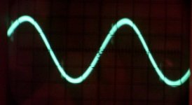
Switching glitches are something else (attached). These result from having less than perfect OPTs, and are unavoidable. If you'll notice, these are occurring far from the x-over point. X-over distortion is the unavoidable consequence of active devices that go highly nonlinear as they approach a cutoff condition (and that means all of them, hollow state and solid state). The only way to avoid that completely is Class A, which you may not want to do, either because your finals can't operate into Class A (e.g. 6BQ6 -- where the best sounding Class A bias is well into red plate territory) or because you're not getting the power you need, or you can't tolerate the heating that will inevitably result (mostly applies to solid state, though there are some hollow state, Class A designs that double for room heaters). Your only other alternative is Class AB with as high a bias current as your finals can tolerate.
From these o'scope pics, X-over is not noticeable at the zero crossings, and that's what you want. Switching glitches can't be avoided unless you get rid of the OPT or try something like a Circlotron designed to keep them out of the OPT. That was overkill, and any decent OPT sounds good anyway, as flaws like these are minimized.
Attachments
Looking back at the SS version in Broskies schematic, imagine the input signal doing a slow ramp from -Max thru crossover to +Max, and visualize what the driver transistors are seeing as feedback on their emitters. For a class A stage, the feedback would be a smooth signal thru the whole ramp, but for a class AB stage the feedback does a smooth ramp up until the crossover region is reached. It then speeds up thru the crossover region, then returns to the normal smooth ramp. This exagerates the crossover error for the feedback, which then tries to smooth it out. Crossover region ends up widened and smoothed. 20 dB (100 X) of improvement in crossover dist. according to Broskies simulation. I've found at least 4 different patents so far on this in SS variants. Edmond Stuart is also using a variation on this in his TMC ppm dist. type SS amps over on the SS forum.
I would go much easier and more straightforward: LTP output stage.
Re: Miles Prower:
"Switching glitches are something else (attached). These result from having less than perfect OPTs, and are unavoidable. If you'll notice, these are occurring far from the x-over point."
Um.., you mean those little fuzzies toward the peaks? Look more like some small transient parasitic HF oscillations, but the trace is too unfocused to tell for sure.
------------------
Wavebourn:
"I would go much easier and more straightforward: LTP output stage. "
But that would mean going class A then, OK for Winter I guess.
Wavebourn:
"I would go much easier and more straightforward: LTP output stage. "
But that would mean going class A then, OK for Winter I guess.
No big deal in such case: class AB with relatively large individual cathode resistors.
Okkam's razor! 😉
Um.., you mean those little fuzzies toward the peaks?
Yes.
Look more like some small transient parasitic HF oscillations, but the trace is too unfocused to tell for sure.
They're not. The pic is of the result of subtracting the input from the output with an op-amp linear subtractor. What's left is the difference (i.e. distortion). It's not a complete null due to phase shift at the test frequency (166Hz). The "little fuzzies" are the result of one side of the PP pair handing off to the other side, as one final goes into plate current cutoff. If you aren't using a linear subtractor, you can't see anything by o'scoping either the primary or secondary, and there are definitely no RF parasitics. ("Snivets" are quite obvious.)
This occurring with 6BQ6s biased to Ip= ~50mA (biased hot: ~17.5W of static Pd -- spec busting as Pd(max)= 12W according to the spec sheet. Since these were originally designed as HD finals, the ratings are very conservative, and so spec busting for audio final operation does no harm.)
Well it's a relief that it takes an op. amp. differencer to see anything. If you look at McIntosh and Gow's paper:
http://www.veiset.net/tech/Mac1949.pdf
They make the "GLITCH" look like the Grand Canyon in figure 2. But seeing that it's caused by leakage inductance (so not even coupled to the output) ringing with distributed capacitance (flyback at tube cutoff), one wouldn't really expect it to couple to the output signal at all (maybe just inter-winding capacitance feedthru). Much ado about not much apparently.
Then some snubbers could be added to knock the HF glitch out too.
In any case, anything that smoothes tube turn off for crossover dist. fixup should also fixup the "glitch" some too. And crossover dist. is the big nuisance for class AB or "B".
Then again, some Edcor P-P OTs I've measured the leakage L on, have a big assymetry in leakage L between the primary sides (to the secondary). I doubt one side even makes the audio HF specification for coupling to the load. This could create a pretty good size "glitch". I think they lowered the Freq. response to 20 Hz, from Hammonds 30 Hz, (using more turns) but did not increase the interleaving to compensate for the now increased leakage L. The outer 60% primary winding section is almost flapping in the breeze.
Last edited:
- Status
- Not open for further replies.
- Home
- Amplifiers
- Tubes / Valves
- 809's in Class B P-P w/feedback