Well life is full of surprises. I am or used to be a die hard Push Pull Amp guy, that was until I made an 807 SE amp (5 watts, no NFB) for a friend. Long story short I am stunned at how good it sounds......I am not sure why !!!! I would like to think it has something to do with the circuit I designed (????) or more likely just the simplicity of SE amps. So now I am in a dilemma since I was about to embark on the building of my own PP amp next month. I need to think it through, is SE the way to go I wonder ????????
Well done! I've been back and fore several times between SE and PP. I tried for years to make my "perfect" 300b amp - never really got there. I think the reason why was cathode bypass caps - always hated them. In the interim I made a really good PP 2a3 amp and thought that was the answer - constant current sinks in the cathode were a good way of biasing. I finally came back to SE with a PSE amp. I hadn't tried that before and it really worked with PSE 4P1Ls in the output. Crucially, I was able to run all the tubes in filament bias so no cathode bypasses, and all transformer coupled. Filament bias works with DHTs so that would be a design choice. I use all DHTs - 26 into 4P1L into 4P1L. Cheap enough if you want to try that for a circuit. Plenty of details on "yet another SE 4P1L" thread. Vocals are magic in SE.
I have had a similar experience, always looking for the "perfect straight wire with gain." The lowest distortion was the holy grail. Then one day I tried a 300B SE amp and it popped my bubble. How could it be? But it's distortion is so high. I could not turn it off. Every cd and record was played again, and I loved it. Then I tried to "Improve" it with lower distortion, better output transformers, better front end... only to come back to the original design - flaws and all. Go Figure.
Thank you guys for sharing your experiences with SE vs PP....I too hate bypass caps on the cathode..... but on this amp I have used 50uf electrolytic (in fact these caps and all the components I salvaged from a 40 year old Oscilloscope).....this amp has been made on the cheap so it defies all the BS about using ultra expensive components. It has given me new insight into amp design and put to rest misconceptions that I have had.
I loved the 1625 (12V equiv of the 807) amplifier I built. Mine was all pentode, even including the driver, with regulated screens. Used loop feedback too. A great little amp and so cheap to build.
Hi CV6045,
I've nearly built an RH807, just need to decide on output transformers. What did you use in your build ?
I've nearly built an RH807, just need to decide on output transformers. What did you use in your build ?
...it has something to do with the circuit I designed (????)...
Well we wouldn't know unless you were to SHARE that schematic!? 🙂
Well we wouldn't know unless you were to SHARE that schematic!? 🙂
+1
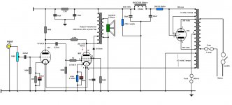
Could you explain the screen grid arrangement (diode, 1uF cap)?Attached is the Circuit Diagram
-
The 150K resistor in the G2 circuit is there to provide a constant current drain of 2m/a through the diode, the capacitor is there to decouple any noise and also add a degree of stability
Could you explain the screen grid arrangement (diode, 1uF cap)?
-
....the capacitor is there to decouple any noise and also add a degree of stability
It also decouples audio signals.
The impedance from screen grid to ground is 160 ohms at 1 kHz and only 16 ohms at 10 kHz.
Is this really designed feature ?
This is the simulated frequency response of the above circuit.
Without 1 uF capacitor from screen grid to ground the response is fully flat.
This is the circuit diagram I used for the simulation:
Without 1 uF capacitor from screen grid to ground the response is fully flat.
An externally hosted image should be here but it was not working when we last tested it.
This is the circuit diagram I used for the simulation:
An externally hosted image should be here but it was not working when we last tested it.
Last edited:
Thank you for the simulation...you are of course correct. On the original design it was noticed that certain diodes generated noise and the cap was used to suppress it. That said on the actual finished article I played around with different diodes and found some that were quiet and did not need any filtering. The circuit I posted shows the cap in circuit when it should have been omitted.
This is the simulated frequency response of the above circuit.
Without 1 uF capacitor from screen grid to ground the response is fully flat.
An externally hosted image should be here but it was not working when we last tested it.
This is the circuit diagram I used for the simulation:
An externally hosted image should be here but it was not working when we last tested it.
I am stunned at how good it sounds......I am not sure why !!!! I would like to think it has something to do with the circuit I designed (????) ?
Strange design: looks just like an RH807 with wrong driver and resistor values.
Plus, several errors that make it sound worse than it should.
Did you really design that one?
- Status
- Not open for further replies.
- Home
- Amplifiers
- Tubes / Valves
- 807 SE Amp