hi!
In an old german "Funkschau" technical journal from 1954, I stumbled over an interesting article // I´m processing this antique reading material in batches... 😀
-> is it allowed to post a scan of this old 1954 article / schemes?
There is also the original article by "Lloyd B. Hust, Radio & Television News, September 1953", may I attach it?
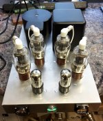
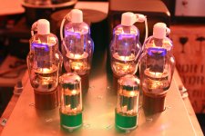
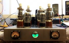
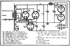
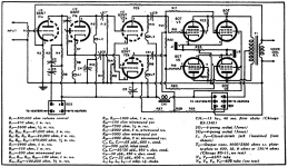
It´s a push-pull monoblock amplifier with 6SN7GT in preamp & phase inverter, and four 807 tubes in the output stage.
Each half side of the 807s are set as triode, and the other in pentode mode.
The idea is to combine the triode advantages at low power with the higher output power of pentodes.
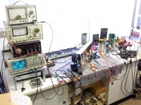
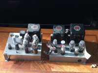
I finished one monoblock so far, but I´m still testing and optimizing 🙂
Hardware:
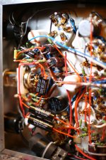
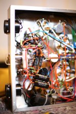
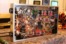
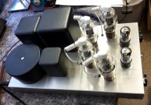
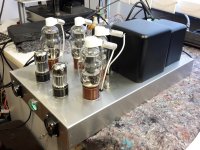
- 250VA toroidal power transformer, custom made (on order)
- PP output transformer 3,5k/4-8-16 ohm
- Chokes 0,5H/300mA and 10H/100mA, stock items from a german seller
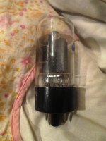
- 807 tubes, NOS russian
- 6SN7GT tubes, NOS RCA
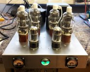
- EM71 magic eye tube, Tungsram, as output level indicator, switchable
- Zener diode stabilization for screen and grid voltage
- A massive ground cupper rail on teflon mounts - eliminates every ground loop 😉
- mA meters to set cathode current and balance, switchable
- Speakon speaker connection, like on all my diy amps - easy and safe plug & play
- I think I might like some side panels made of dark oiled wood 🙂
Specs:
- Plate voltage 450V
- Zero signal plate current 110mA (triodes only conducting)
- Max. signal plate current 256mA (all tubes conducting)
- Screen voltage 300V
- Grid voltage -45V
- Max. output power 15V @ 1kHz and 8Ohm resistive load , that´s nearly 30W
- 0,18% THD @1kHz and 1W power
- 0,36% THD @1kHz and 5W power
- 0,62% THD @1kHz and full output power
- The frequency response still needs to be optimized and measured
At first I used two russian 6SN7GT tubes, but they had a really bad performance.
Very sensitive to microfonic, and a strong hum from the AC heated filament. After that, DC heating was applied.
Two Electro Harmonix 6SN7GTs with new production date were not much better. AC hum and over 2% THD speaker output .
I switched to american NOS RCA 6SN7GT tubes, and they went perfect! They absolutely fit in 1950s time, with a really nice electrical and mechanical quality.
No hum, immediately less THD - but quality has its price...
Maybe I try some other 807 brands some time.
It was necessary to add HF coils (made of 1,5mm silver wire) to the 807 anode caps.
Otherwise some wild HF oscillations appeared at a specific output level, perhaps because of poor russian 807 specimen.
20Ohm resistors also worked.
I completely revised the wiring with shorter connections. Maybe now it runs without HF coils.
It is difficult to judge the mono sound at only one speaker.
But the amp plays quite soft and warm, without sharp edges, powerful and not intrusive.
If everything really works to my satisfaction, a second monoblock will be made for stereo playback ...that's the decision I have to make now.
greetings, Tobias 🙂
In an old german "Funkschau" technical journal from 1954, I stumbled over an interesting article // I´m processing this antique reading material in batches... 😀
-> is it allowed to post a scan of this old 1954 article / schemes?
There is also the original article by "Lloyd B. Hust, Radio & Television News, September 1953", may I attach it?
It´s a push-pull monoblock amplifier with 6SN7GT in preamp & phase inverter, and four 807 tubes in the output stage.
Each half side of the 807s are set as triode, and the other in pentode mode.
The idea is to combine the triode advantages at low power with the higher output power of pentodes.
I finished one monoblock so far, but I´m still testing and optimizing 🙂
Hardware:
- 250VA toroidal power transformer, custom made (on order)
- PP output transformer 3,5k/4-8-16 ohm
- Chokes 0,5H/300mA and 10H/100mA, stock items from a german seller
- 807 tubes, NOS russian
- 6SN7GT tubes, NOS RCA
- EM71 magic eye tube, Tungsram, as output level indicator, switchable
- Zener diode stabilization for screen and grid voltage
- A massive ground cupper rail on teflon mounts - eliminates every ground loop 😉
- mA meters to set cathode current and balance, switchable
- Speakon speaker connection, like on all my diy amps - easy and safe plug & play
- I think I might like some side panels made of dark oiled wood 🙂
Specs:
- Plate voltage 450V
- Zero signal plate current 110mA (triodes only conducting)
- Max. signal plate current 256mA (all tubes conducting)
- Screen voltage 300V
- Grid voltage -45V
- Max. output power 15V @ 1kHz and 8Ohm resistive load , that´s nearly 30W
- 0,18% THD @1kHz and 1W power
- 0,36% THD @1kHz and 5W power
- 0,62% THD @1kHz and full output power
- The frequency response still needs to be optimized and measured
At first I used two russian 6SN7GT tubes, but they had a really bad performance.
Very sensitive to microfonic, and a strong hum from the AC heated filament. After that, DC heating was applied.
Two Electro Harmonix 6SN7GTs with new production date were not much better. AC hum and over 2% THD speaker output .
I switched to american NOS RCA 6SN7GT tubes, and they went perfect! They absolutely fit in 1950s time, with a really nice electrical and mechanical quality.
No hum, immediately less THD - but quality has its price...
Maybe I try some other 807 brands some time.
It was necessary to add HF coils (made of 1,5mm silver wire) to the 807 anode caps.
Otherwise some wild HF oscillations appeared at a specific output level, perhaps because of poor russian 807 specimen.
20Ohm resistors also worked.
I completely revised the wiring with shorter connections. Maybe now it runs without HF coils.
It is difficult to judge the mono sound at only one speaker.
But the amp plays quite soft and warm, without sharp edges, powerful and not intrusive.
If everything really works to my satisfaction, a second monoblock will be made for stereo playback ...that's the decision I have to make now.
greetings, Tobias 🙂
Attachments
-
 01-Aufbau.jpg671.7 KB · Views: 1,052
 -
 11-Verschaltung.jpg635.7 KB · Views: 464
 -
 10-Verschaltung.jpg566.4 KB · Views: 511
 -
 07-Verschaltung.jpg817.8 KB · Views: 627
 -
 06-Verschaltung.jpg647.9 KB · Views: 661
 -
 06-Betrieb.jpg588.5 KB · Views: 494
 -
 05-Aufbau.jpg499.4 KB · Views: 939
 -
 04-Aufbau.jpg630.7 KB · Views: 1,162
 -
 03-Aufbau.jpg621.1 KB · Views: 1,062
 -
 02-Aufbau.jpg444.6 KB · Views: 997
I have a pair of RCA MI-12188 monos which uses PPP 807. Sounds good!
You should build a pair.
Matching plate current is critical in cathode biased circuits or red plating in one tube is possible.
You should build a pair.
Matching plate current is critical in cathode biased circuits or red plating in one tube is possible.
After 64 years there is no copy right imo, patent pending is 15 years in US.hi!
In an old german "Funkschau" technical journal from 1954, I stumbled over an interesting article // I´m processing this antique reading material in batches... 😀
-> is it allowed to post a scan of this old 1954 article / schemes?
WIMA MKS 10% precision 😱
Last edited:
WIMA MKS 10% precision 😱
haha, I knew someone would notice! 😀
There are Wimas in the power supply only. As filter capacitor, parallel to the electrolytic capacitors.
In the audio pathway, there are axial polypropylene caps from a trusted german manufacturer.
Perhaps this link is all that is needed for the Radio TV News:
http://www.americanradiohistory.com/Archive-Radio-News/50s/Radio-News-1953-09.pdf
http://www.americanradiohistory.com/Archive-Radio-News/50s/Radio-News-1953-09.pdf
Using triodes throughout the amplifier and an appropriate topology like the Williamson circuit produces excellent sound. There are still a pair of triode amps in my living room with triode connected KT88's supplying about 20 watts class A in my lounge. The only problem now is the lifetime plus expense of KT88's, as others have no doubt noticed. Hence some class A transistor amps sit nearby (JLH cct). These sound just as good to my ears.
Hi Tobias, nice work there and obviously a huge amount of effort! That's one of the beefiest ground busses I've seen inside an amp.
As this is effectively a Williamson amp, the performance will depend a lot on the output transformer and the feedback level.
Hust's circuit uses 7k5 for feedback resistor, whereas stock Williamson uses 3k4 for an 8 ohm output impedance, so 20dB stock feedback will be down to I'm guessing around 10dB - its a bit tricky to calculate, which I haven't done.
The lowered feedback sort of allows the extra CR High pass filter of the first-to-second stage to not cause low frequency instability, and will depend on the output transformer primary inductance, so some caution is advised.
The step network on the input stage is also modified, which with the output transformer, will probably dominate the high frequency response.
I've found that slipping a few emi suppressor ferrite tubes/beads over the 807 grid, screen and anode wires that connect at the terminals provides adequate impedance to control oscillations, plus a 10 ohm 1-2W resistor will typically fit under the ceramic anode cap (certainly less noticeable and a lot safer than those coils!).
It is certainly worth tube rolling 6SN7's for the driver stage to choose the lowest distortion valve you have - I found a fair bit of variation when I did that. Same with the 807's, if distortion is a main concern for you. Hopefully making distortion measurements with your Leader meter is not too onerous - it's certainly very easy with modern software tools like REW.
How have you done the screen regulation, and what pentode screen peak current are you coping with?
Ciao, Tim
Hust extended class A amplifier
I just discovered tonight that I have had this very amplifier for several years. I got it on the bench about a week ago, thinking the whole time I've owned it that it was a (BIG) standard Williamson. Once on the bench I discovered the unusual output tube connection.
I Replaced a few capacitors and it sounds very good. Tonight I looked on the internet for "Triode Pentode Williamson Amplifier" and found this thread, and Tobias' reference to the article from 1953.
I have several Williamson amplifiers, and this is one of the best sounding. Now that I know it's intended design, I will try it out more thoroughly. I also discovered that Mr. Hust was a teacher and owned a radio and TV repair shop in Utah, USA.
Thank you Tobias!
Attachments
Wow!
The power supply chassis has a multi pin output connector (High Voltage, not just filaments).
If the connector pulls out from the amplifier chassis, be sure not to contact any of the pins from the power supply.
That could be deadly.
OK for 1953, but not passing safety standards for 2020.
In 2020, the pins have to come out from the amplifier.
Just reverse the sockets and plugs of the amp and power supply.
Safety First!
Last edited:
Gnoobie question here... I don't remember seeing 1mh chokes used like this in my studies. Are these just another way to stop RF? Or do they address oscillation instability? I noticed no grid stoppers on the 6SN7's. Why do we not see this part more often used like this? 1mh, 500ma, 600v chokes are pretty cheap on eBay, a bag of them for breadboarding might be worth it?
I just discovered tonight that I have had this very amplifier for several years.
I have several Williamson amplifiers, and this is one of the best sounding....
Mr. Hust was a teacher and owned a radio and TV repair shop in Utah, USA.
So he is the author of this fundamentally very very silly idea?? 🙄
No, Sterling is the originator of the idea of melding triode and tetrode characteristics.
https://www.americanradiohistory.com/Archive-Radio-Electronic-Engineering/Radio-Electronic-Engineering-1951-05.pdf
No distortion results are presented as this was early days when very few people could measure HD below 0.1%, and even fewer could measure IMD. So from that perspective, there are no measurements to substantiate or disprove the technique.
No distortion results are presented as this was early days when very few people could measure HD below 0.1%, and even fewer could measure IMD.
No, the thrust of the (silly idea) article is nothing to do with distortion, it's to claim you can get triode behaviour with pentode power thru an "extended class A".
They then ramble on about the seeming neccessity to use the 807 for this. (presumably because they were literally giving the things away in those days!)
However the whole article shows it's plain daft, because they (also) claim they can the same or better results by driving triodes in A2 (like AB2), by driving them into grid current.
The main (silly) objection they make to doing this, is by claiming those triodes are too old and mainly DHT.
In the day we can use modern high current TV tubes, this sort of idea seems to come from some outer planet like Pluto or even Uranus! 😀
You can get an ultra cheap triode that does the job, 1/4 the size, far higher performance, much more linear and without that damn stupid top cap, and it's OCTAL.
here it is:-
You can get them for 1USD. (sorry they're now 4-5$ in 2020, 3$ for the 12v version, also in 17v &25v )
It's called the 6 or 12AV5, it can take massive over voltage/overloads because anode is on pin 5, screen on 8.
..rumors that the 6AV5 was a possible substitute for the 6B4. Since the 6B4 is an octal version of the 6A3, which is a 6 volt version of the 2A3. some people were calling the 6AV5 a modern version of the 2A3
Seems to me this forum, is becoming more and more about "why do it simple, when we can make it massively-stupidly overcomplicated".
There's some concept going out of fashion called "common sense", being an oxymoron, cos it's not very common!
Attachments
Last edited:
You can get an ultra cheap triode that does the job, 1/4 the size, far higher performance, much more linear and without that damn stupid top cap.
here it is:-
You can get them for 1USD.
It's called the 6/12AV5.
Indeed. In which case, why not go all the way toward common sense and efficiency with a device one-hundredth the size and requiring a tenth of the drive capability?
Here it is: -

The answer is, of course, because TOOBS!!! Very little about diy audio is rational - why would topology and component selection differ?
If you haven't tried the configuration or can't go in to that configuration in any more detail than it is a 'silly idea', then that kind of review seems pointless. Sterling goes in to a few other technical areas, but that is off-topic for this thread so seems silly to add in.
We all have 70 years on that article, and could similarly say it is silly because they don't use silicon transistors which are cheaper, have far higher performance, are much more linear and don't have a top cap.
We all have 70 years on that article, and could similarly say it is silly because they don't use silicon transistors which are cheaper, have far higher performance, are much more linear and don't have a top cap.
Well, these last 2 posts are the perfect illustration of "oxymoron" behaviour, inc printing an A4 size photo of a device.
Nobody suggested transistors were better or more linear, or don't you bother to read linked articles?
I would suggest the author of the article is likely to know a lot more about it than you, as he worked in the industry.
Nobody suggested transistors were better or more linear, or don't you bother to read linked articles?
I would suggest the author of the article is likely to know a lot more about it than you, as he worked in the industry.
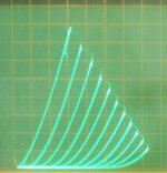
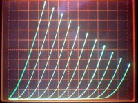
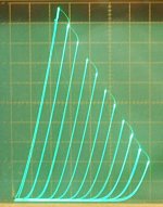
Here are some triode mode curves for 6AV5/6BQ6GA/12BQ6GTB. (1st pic below) I suspect 2A3 looks a little better. (then again, maybe not, similar curve roll-over on the datasheet) I don't have one to test here. 2A3 Datasheet from Frank's list below.
https://www.diyaudio.com/forums/tubes-valves/211254-magnificent-television-tubes-61.html#post4618404
12/6GE5 / 12/6JN6 look to have similar curves as the 6AV5/6BQ6, but an 18 Watt rating, versus 11 Watt for the 6AV5.
Seeing how the 2A3 has some noticeable curve rollover compared to a more ideal triode (2nd and 3rd pics below), I wonder if the 2A3 just has the right amount of 2nd harmonic to be "euphonic".
Attachments
Last edited:
"Seems to me this forum, is becoming more and more about "why do it simple, when we can make it massively-stupidly overcomplicated". Every post I've read of yours 6vheater says the same thing, your all f***in idiots and I know better. Yawn.
Andy.
Andy.
Last edited:
- Home
- Amplifiers
- Tubes / Valves
- 807 Extended Class A Amplifier [1954 style]