a big number of them still believe that AC in the heaters is the best.
so if one does not use Rod's regulators, then that means that they believe that ac heating is the best?
there is a sea of difference between saying AC heaters are the best and that of saying AC heaters work.....
so if one does not use Rod's regulators, then that means that they believe that ac heating is the best?
It has nothing to do with Rod's regulators, even when I cannot design anything better, anyway he do not need any propaganda.
there is a sea of difference between saying AC heaters are the best and that of saying AC heaters work.....
Classical Electrodynamics tells us that a time varying voltage/current on the filament induces a time varying voltage on the grid.
As a consequence, if you feed the filament with AC you have unavoidably induced AC in the grid. This is a fact, a caprice of nature if you want.
If you feed the filament with DC, induced voltage in the grid is zero. This is a fact too.
As I do not want induced AC in the grids, I always use DC on the filaments.
If you like to have induced AC in the grids, for any reason, good for you, and at this high sincerely I do not care.
Last edited:
well as far as i can see, it is only you who mentioned "AC heating is the best", it is on your post...
well as far as i can see, it is only you who mentioned "AC heating is the best", it is on your post...
You can see it as you want, but please stop with this kind of bullying, you are making the discussion personal instead of technical. 🙂
With respect to the non-liner anode (filament) voltage vs current, Van Der Bijl states "In fact the full solution for the curved characteristic has not yet been given. On the other hand, when the tube is used as a modulator or detector of high frequency oscillations the curvature of the characteristics is actually made use of."
This is discussing inter-modulation used for either frequency multiplication, Inter-modulation, or detection.
It seems evident from his analysis that ac filaments are a source of inter-modulation of the filament source frequency and any grid applied signals.
This is discussing inter-modulation used for either frequency multiplication, Inter-modulation, or detection.
It seems evident from his analysis that ac filaments are a source of inter-modulation of the filament source frequency and any grid applied signals.
while i do not doubt the efficacy or veracity of such claims,
my basic question is how much of that is audible?,
i would like to see actual testing, or listening tests to demonstrate audibility...
my basic question is how much of that is audible?,
i would like to see actual testing, or listening tests to demonstrate audibility...
that is an amplifier Anatoly isn't that?
Q1 is the series pass and Q2 is an error amplifier...
Yes. An error amplifier loaded on 300k, and a source follower with voltage on the gate limited by 12V protecting Zener. 0.022 Ohm resistance. Simple, but functional, like AK-47 machine gun.
my basic question is how much of that is audible?
I have read somewhere that amplifiers with AC on heaters have a "warmer" and "richer" sound, with more harmonic content, maybe this is the famous "tubey" sound that most people love.
I prefer that my amplifiers do not have a "sound" and very often I reach the target, it is very nice when you do not hear them, just the music.
i would be more interested in what you yourself actually experienced....😎
in our local forums in manila, i tell people, i may be able to tell you the hows and the whys of things, but how you should enjoy your music, i am sorry, that is not for me to say...
i would be more interested in what you yourself actually experienced....😎
That is not your original question, but, as this kind of distortion can be avoided from the beginning as a design choice, and it is actually my experience, I have not experienced IMD due to AC on the heaters because I only use DC. 😎
in our local forums in manila, i tell people, i may be able to tell you the hows and the whys of things, but how you should enjoy your music, i am sorry, that is not for me to say...
Perhaps you may be able to tell people the hows and the whys of IMD due to AC heaters, which is what Rod has been doing here. 😉
This back and forth is pointless. I will do measurements and report back, even if i am wrong.
Let's settle on this offer. We get the details of how the measurements were made so we if we like can repeat them. When we have seen the figures we can implement them if we wish and listen for ourselves and decide what fits each one. A fair deal and we can go on - probably in different directions but that is not neccessarily a bad thing 🙂
Regards
Has anyone used one of the dc to dc buck boost, or buck converters that are now widely available for almost no money to power dh filaments?
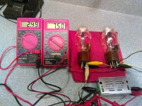
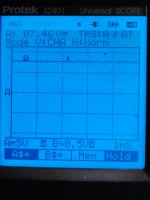
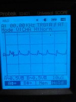
Out of curiosity, I hooked up a couple of 801A's to one that is widely available in the $5 USD range. DC output looks Okay, there is ac switching noise of about 0.2 volt at about 120 kHz. The scope shots are with it hooked up to the 801A's.
This one is supposed to regulate voltage and current. It held voltage to about 0.01 volt over an eight hour span. Not sure about the current regulation, it has a current control that has to be adjusted for the load, but it may be current limiting. Or something else. No documentation, of course.
Win W5AJG
Attachments
Has anyone used one of the dc to dc buck boost, or buck converters that are now widely available for almost no money to power dh filaments?
Out of curiosity, I hooked up a couple of 801A's to one that is widely available in the $5 USD range. DC output looks Okay, there is ac switching noise of about 0.2 volt at about 120 kHz. The scope shots are with it hooked up to the 801A's.
This one is supposed to regulate voltage and current. It held voltage to about 0.01 volt over an eight hour span. Not sure about the current regulation, it has a current control that has to be adjusted for the load, but it may be current limiting. Or something else. No documentation, of course.
Win W5AJG
I used this one
DC-DC Buck Converter Module LM2596 Constant Current & Voltage Adjustable Module | eBay
for 71A filament on a breadboarded driver stage. Worked with no problem. Can be used as constant voltage or constant current regulator. I was thinking of ripping off the output rectifier and feeding the 150 KHz AC directly to the filament, but haven't done it yet.
Using these DC-DC converters, one should treat their advertised current capability with a grain of salt. Depending on input and output voltages, the converter IC may heat. Adding a heat sink may be helpful.
Let's settle on this offer. We get the details of how the measurements were made so we if we like can repeat them. When we have seen the figures we can implement them if we wish and listen for ourselves and decide what fits each one. A fair deal and we can go on - probably in different directions but that is not neccessarily a bad thing 🙂
Regards
I think it would be great for me to have some feedback on the design of this test, so as to avoid mistakes invalidating the results (like comparing SE and PP amps).
I will measure three 6A3 tubes from different manufacturers. The circuit will be SE power stage with fixed bias operating at 250 V 60 mA. Fixed bias will be applied through 300 H grid choke, shielded electrically and magnetically. Input from two pots to allow different signal ratios. B+ from choke input supply.
Filament supply will be either lead battery or conditioned AC (below).
Two op-amp battery-powered sine wave generators will provide 0-5 V of 400 Hz and 1000 Hz signals. Output from OPT secondary (3 K:4 Ohm) loaded with 4 Ohm resistor will be fed into PC sound card, and spectra obtained using free software.
Power lines in the cities are so contaminated that doing a clean test of this kind is virtually impossible. As a remedy, the tests will be done in my countryside house, where the power is supplied from an independent high voltage transformer not shared with other properties. In addition, there is a passive power waveform conditioner for dedicated audio outlets. No switch mode supplies, LEDs, fluorescent lights, or motors will be in use during the test. Computer will be battery-powered laptop.
I have only one OPT for this experiment, but it may be not suitable. The minimum primary inductance to do the test right is about 40-50 H; I am not sure my transformer has enough.
The questions to answer shall be how much IMD between 1000 and 400 Hz occurs at low power, and compare it to IMD levels due to residual filament hum.
Critiques? Suggestions?
If you are prepared to go to some trouble to make some careful measurements, that would be very commendable.
I agree with Turbon - the results will get wider acceptance if the detailed method is detailed and clear, and can be readily reproduced.
To achieve this, some extra measurements are needed.
1. Real-world construction of ac-heated amplifiers means taking the mains as it comes. So measurement using an ordinary ac supply (transformer) would be needed. In the city, too.
Noise on ac-supplies is difficult to filter out, without going to more cost than a properly-implemented current-drive dc solution.
With dc regulation, noise reduction is much simpler, and my design readily achieves noise levels down to the low microampère region.
Using a synthesized & conditioned mains may help to separate out the contributions of different noise sources may be interesting theoretically, but if real-world applications are a lot worse because of noise, the guidance for practical ac-vs-dc choice could be badly misleading.
Having to recreate the synthesized ac-heating makes reproducing/checking the experiment unduly difficult - this again can be addressed by heating with a trafo, as a separate measurement set.
2. The thread topic is concerned with the choice between ac and dc heating. Real-world applications of DHTs run them from low-levels all the way up to clipping, so confining the test to low-output levels is meaningless for most constructors. I see that your interest is centred on low-power, but I don't think anyone else's is.
Last edited:
- Status
- Not open for further replies.
- Home
- Amplifiers
- Tubes / Valves
- 71A Tube Filament: AC or DC ?