Can the grid stopper before the 71A be higher in value, say 27K? I have a nice pair of 27K resistors that I would enjoy using in this position.

Hmmm... I just learned something. I found a post by 6A3sUMMER from a couple years ago, conversing with kodabmx about battery bias. (diyAudio threads hold so much info!) It seems there are people who've successfully used a battery in series with the grid for fixed bias. So let's go with that here. That would look like this:

68 ohms in series with a 100 ohm trimpot.
68R and 100R,
R4 could be 68R, 47R 62R, or 56R, or even 33R. You'd have to account for that in your Ohm's Law calculating when you adjust Rset for the MOSFET to get the plate current you're after (which is about 14mA, I think).
68R and 100R,
R4 could be 68R, 47R 62R, or 56R, or even 33R. You'd have to account for that in your Ohm's Law calculating when you adjust Rset for the MOSFET to get the plate current you're after (which is about 14mA, I think).
Series battery bias as in Post # 39 can only Very mildly charge the battery, only if there is low grid current at the positive peak of the music.
The battery lasts for the shelf life of the battery (I used battery bias years ago, in the series configuration).
Do not forget to use the grid stopper, as in Post # 43.
The battery bias as in Post # 40 does alternately Discharge and Charge the battery when Any Signal is present. Yes, low current.
Just my $0.03
There's something about the battery in series with the tube grid for fixed bias that I'm worried about.
As the battery ages, its internal resistance will go up and its voltage will go down.
As the battery's voltage goes down, the tube's grid will be drawn closer to ground potential (0V).
This means the grid bias will be going more positive, and the tube will be biased 'hotter'.
However, with the CCS plate load holding the plate current to around 14mA, the plate voltage will go up as the grid voltage goes more positive.
At what point will the grid get to near zero bias and the plate voltage rises high enough so that the MOSFET drops out nearing zero volts drain to source?
What would the failure mode be should that happen? I figure the tube would red-plate for sure, and the grid would start to draw current, so it could be damaged that way. Anything else?
Am I being a worrywart? Of is the above a valid concern?
rongon,
I designed and built a battery tester that measures the battery's internal impedance.
Compare the grids very high impedance (AC and DC); versus the batteries very low impedance (AC and DC)
That is like Pluto's Orbit Diameter, grid impedance; versus Mercury's Orbit Diameter battery impedance.
If your tubes have Leaky Control Grids, then . . .
replace the tube,
design with a less leaky tube model type,
Or,
Do not use Battery Bias (But please note your grid will be in a higher impedance situation versus battery impedance).
Most circuits of most grids are much higher impedance (driver, RC coupling, Rg, grid bias supply series resistor or Potentiometer, etc.
Most batteries shelf life is more years than those who replace their tubes every 7 years.
Which is more expen$ive, batteries or tube$?
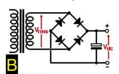
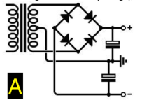
OK, so I have ordered all the remaining few parts. I want to create a simple solid state rectifier ( in lieu of a tube rectifier). I have never done this before and the internet shows different schematics depending upon the power transformer. My Power Transformer is 165-0-165. I am assuming that the 0 is the center tap, correct? If so, which of the schematics (A or B) be appropriate? Also, with solid state rectifiers, can I use an LCLC or must I use a cLCLC?
Attachments
What DC voltage(s) do you want to end up with?
That's the question.
165-0-165 is center-tapped, as in your image ending in '10'. However, I don't think you want to wire yours up that way. You'd end up with one positive and one negative DC voltage. Do you need a negative supply?
A transformer with a 165V-0-165V secondary is the same thing as a 330VCT (330V center-tapped) secondary. Same thing, different names.
I think at this point you might want to read up on how a full wave rectifier with center-tapped secondary works.
https://www.valvewizard.co.uk/bridge.html
https://www.physics-and-radio-elect...and-circuits/rectifier/fullwaverectifier.html
Example choke input power supply using center tapped transformer with full wave rectification:

A decent approximation for the output voltage you can expect for a choke input supply at full load (with the tubes warmed up and everything conducting) is:
VDC = Vpk * 0.9
In this case, 165V * 0.9 = 148.5V DC
You'll now need to know the current drawn by the powered circuit and the DC resistance of the chokes so you can calculate how much voltage will be dropped across the chokes you'll be using. If the chokes have DCR of 140 ohms and each 71A draws 20mA of plate current, each choke that's common to both channels will drop 5.6V. With two chokes in a row, that's 148.5V - 11.2V = 137.3V DC for the B+ to each 71A.
That's the question.
165-0-165 is center-tapped, as in your image ending in '10'. However, I don't think you want to wire yours up that way. You'd end up with one positive and one negative DC voltage. Do you need a negative supply?
A transformer with a 165V-0-165V secondary is the same thing as a 330VCT (330V center-tapped) secondary. Same thing, different names.
I think at this point you might want to read up on how a full wave rectifier with center-tapped secondary works.
https://www.valvewizard.co.uk/bridge.html
https://www.physics-and-radio-elect...and-circuits/rectifier/fullwaverectifier.html
Example choke input power supply using center tapped transformer with full wave rectification:
A decent approximation for the output voltage you can expect for a choke input supply at full load (with the tubes warmed up and everything conducting) is:
VDC = Vpk * 0.9
In this case, 165V * 0.9 = 148.5V DC
You'll now need to know the current drawn by the powered circuit and the DC resistance of the chokes so you can calculate how much voltage will be dropped across the chokes you'll be using. If the chokes have DCR of 140 ohms and each 71A draws 20mA of plate current, each choke that's common to both channels will drop 5.6V. With two chokes in a row, that's 148.5V - 11.2V = 137.3V DC for the B+ to each 71A.
Last edited:
Nice chokes, with very low DCR. Not as much voltage will be dropped.
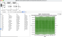
Have you simulated that LCLC filter in LTspice or similar? How's the resonance situation look? Do you need to add some series resistance to tame subsonic resonances? That's often the case with cascaded LC filters.
Have you simulated that LCLC filter in LTspice or similar? How's the resonance situation look? Do you need to add some series resistance to tame subsonic resonances? That's often the case with cascaded LC filters.
A quick simulation shows that your LCLC filter's ripple rejection is really good, but it also reveals a couple of large subsonic resonances, which are to be expected with LC filters with very low DCR. +29dB at 3.5Hz and +14dB at 11Hz. The second one is especially worrisome because it's right where you'd expect a cartridge-tonearm resonance to fall. (Only relevant if you play vinyl records.)

Is that a valid test? I don't know. But I always run that on power supplies I plan to build so I can try to tame those resonances.
A while ago, I built a 12AX7 phono preamp with a passive CRCRC power supply. It turned out to have a rapidly rising impedance at subsonic frequencies that required a lot of decoupling from the first stage to kill some weird booms and rumbles that would poke through while playing records. That taught me to look out for these things, and made me respect regulated supplies a lot more.
Last edited:
This is what I get if I change it to an LCRC with much higher value electrolytic capacitors.

As you can see, changing the second filter section to an RC and increasing the capacitance values by 10X has suppressed those resonances.
Would you hear it? Would it be 'better'? I don't know.
I built a little SET headphone amp with this kind of LCRC filter using 330uF 250V electrolytic capacitors and it turned out really quiet (no hum at all, even with AC heaters) and plays nice bass.
Last edited:
Thanks for running these simulations. Yes, 11hz is typical of tonearm resonances and I plan on using LPs once my analog rig gets stood up. I do have 250uF and 450uF cd-link caps. What is the purpose of 0.22u C3?
I hope this is helping and not leading you astray.
C3 helps suppress flyback from the choke. Helps keep voltage spike in check at power up and power down. It doesn't raise the output voltage, but... You could use a larger value there to bring the voltage up a little. But that's changing the subject...
DC-Link caps would be nice. But they're very large, right? Do you have the room?
My point about the resonances was that cascaded LC filters (LCLC) will have worse resonances than an LCRC. Chokes have subsonic resonances, resistors do not. Increasing the value of the capacitors can reduce the amplitude of those resonances, but to get rid of the resonances you need to add series resistance.
Everything is a compromise.
The best way to do this would be to use a capacitance multiplier or even a regulated power supply. But here come the transistors...
Last edited:
It is the other way around. As the tube tries to pull more current the voltage drop across the CCS will increase, and plate voltage will decrease.There's something about the battery in series with the tube grid for fixed bias that I'm worried about.
As the battery ages, its internal resistance will go up and its voltage will go down.
As the battery's voltage goes down, the tube's grid will be drawn closer to ground potential (0V).
This means the grid bias will be going more positive, and the tube will be biased 'hotter'.
However, with the CCS plate load holding the plate current to around 14mA, the plate voltage will go up as the grid voltage goes more positive.
At what point will the grid get to near zero bias and the plate voltage rises high enough so that the MOSFET drops out nearing zero volts drain to source?
What would the failure mode be should that happen? I figure the tube would red-plate for sure, and the grid would start to draw current, so it could be damaged that way. Anything else?
Am I being a worrywart? Of is the above a valid concern?
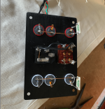
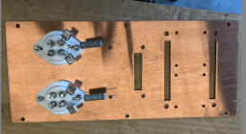
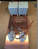
Update. Ready to test the pre-amp. Photos of the build work. I am trying AC filament supply, but have a DC battery solution if the hum is unacceptable.
Q: What is a good/acceptable output noise/hum level?
Q: What is a good/acceptable output noise/hum level?
Attachments
- Home
- Amplifiers
- Tubes / Valves
- 71A preamp design