Not much inductance? I measured two such transformers. One, the smaller, was 70H, the other 50H. These were 70V autoformers with taps used as attenuating and impedance matching transformers.
70H really? How did you measure? Who makes them and what model# because they seem to be much different then what I have on hand.
I will dig mine out and take measurements again.
70H really? How did you measure? Who makes them and what model# because they seem to be much different then what I have on hand.
I will dig mine out and take measurements again.
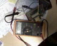
Inductance was measured at 60 Hz by connecting in series with a reference inductor, applying low AC voltage from a transformer (6 VAC), and measuring AC voltages on the inductors.
This is the transformer with 70 H winding:
Atlas Sound AT10 Volume Control - Stainless Steel, | eBay
This is the one with 50 H winding:
Atlas Sound AT100 100W Auto Transformer Speaker Volume Control Stainless Steel | eBay
10 W and 100 W ratings of these transformers are funny. Transformers use the same laminations, with 100 W stack ~1.5 times higher. I took apart one of the 10W transformers, it had 1,800 turns.
Inductance was measured at 60 Hz by connecting in series with a reference inductor, applying low AC voltage from a transformer (6 VAC), and measuring AC voltages on the inductors.
If the AC voltage across the primary winding under test was well below 6V, then the 'nominal' primary inductance could be noticeably higher than measured, given that most referenced primary inductance values are at 5VAC or higher.
The OEP D29A100 manufacturer specifications are: primary inductance 3.81H , secondary inductance 6.5 mH measured at 1 KHz, 0.27V.
That's not too bad, Edcor XSE15-8-5K is specified at 3H primary inductance.
A quick update: I actually tried it on a small SE project with dry battery radio tubes (2P2P , DL91 ; DL96). It works, but distortion is noticeable. It is back in the drawer now. Can't be used as PP output transformer because it does not have a center tap.
pcan, did you get to try a few DC bias settings through the primary to see how distortion and output power at clipping varied?
Several years ago there was a Hundred Buck Amp Challenge in the instruments and amps forum. The idea was to design and build a low buck guitar amp. I designed a 4 watt and a 20 watt guitar amp and tried all sorts of repurposed iron as OPT's. All experiments were P-P since SE really needs a gapped OPT, and tubes are cheaper than iron.
The absolute best $5 ($4 at the time) OPT I tested was this one:
https://www.parts-express.com/70v-10w-speaker-line-matching-transformer--300-040
I used 32ET5 output tubes because the were, and still are $1 each, but any similar sized tube should work. I got just over 4 watts at clip on 165 volts B+. THD was under 2% at 2 watts and 1KHz. It works great over the guitar's 80 Hz to 5 KHz range, just don't expect 20 Hz from this thing.
Connect B+ to the brown primary wire. Purple and black are the plates. Try the 4 and 8 ohm secondary taps to see which works the best in your application. I got about the same maximum power either way, but installed a switch since the distortion profile was quite different when driven about 20 dB into clipping.
The 20 watt amp used this one:
AN-0209 - 25VA 9V Transformer - AnTek Products Corp
I used UL84 tubes (a 45 volt 6CW5, but cheap) and connected the 8 ohm speaker to paralleled 9 volt secondaries. Limited testing was done since the amp design was plagued with microphonics and never finished. This was due to a high gain preamp and no quiet UCC85 tubes (again cheap) could be found. The amp was a real screamer, but the amp and speaker could not coexist. It will be rebuilt with real guitar amp tubes some day.
I will make other tests on the output transformer and some measurements later, when the amp schematic will be finalized. There is very a faint hum that i want to remove, and I suspect magnetic coupling between power and output transformers. Since i removed the output transformers from the chassis already, I remembered this thread and I tried a pair of D29A100 I had around. They are 38:1 between the full primary (tap 0-1) and the 4 ohms secondary; my speakers are between 4 and 6 ohms. The reflected primary impedence is therefore in the ballpark of the requirements of the tubes I was working on. This transformer is ungapped but core is much bigger than the usual 100V transformer, and plate current is 7mA only. The amplifier is a simple voltage gain stage (DAF96) followed with the DL91 output tube, with a little bit of global feedback from the secondary winding of the output transformer back to the grid of the preamp tube. Very simple but it works. Compared to a standard SE transformer I'm using now, the OEP D29A100 does have slightly less low frequencies (but still plenty) and no obvious issues at least up to 16 KHz (my ears stops working there). It could be called a satisfactory result already. The distortion is the same kind I hear from the cheapest china amplifiers or vintage tube PA amplifiers, and it is the same at all volumes. Unnatural, slightly unpleasant tones mainly from organ and brass instruments on classical music; strings are mostly OK-ish and guitar sounds dont'have any issue at all. My scope is out of commission at the moment so I cannot get a picture, but when I get this feeling, usually the distortion is over 5% and the square wave response is bad.
Inductance was measured at 60 Hz by connecting in series with a reference inductor, applying low AC voltage from a transformer (6 VAC), and measuring AC voltages on the inductors.
This is the transformer with 70 H winding:
Atlas Sound AT10 Volume Control - Stainless Steel, | eBay
This is the one with 50 H winding:
Atlas Sound AT100 100W Auto Transformer Speaker Volume Control Stainless Steel | eBay
10 W and 100 W ratings of these transformers are funny. Transformers use the same laminations, with 100 W stack ~1.5 times higher. I took apart one of the 10W transformers, it had 1,800 turns.
It is interesting... I bought this ones and measured 360 milihenry max
5 Pack Rotary Speaker Volume Controls Home Speakers Wall Mount Control (New)
> I bought this ones and measured....
One is for 70V and one seems to be 4/8 Ohm.
70V and 100 Watts is 50 Ohms, much higher than direct speaker impedance.
0.36H at 50Hz is >100 Ohms, so several of these may be run parallel on a 8 Ohm output (if you do not turn-up more than one).
50+H does seem odd for 70V system.
One is for 70V and one seems to be 4/8 Ohm.
70V and 100 Watts is 50 Ohms, much higher than direct speaker impedance.
0.36H at 50Hz is >100 Ohms, so several of these may be run parallel on a 8 Ohm output (if you do not turn-up more than one).
50+H does seem odd for 70V system.
I bought a pair of 10W transformers, measure.
One on 100 Hz measures 6 Henry, another one measures 6.2 Henry. As I expected for 100V transformer. No free lunch, except in a mousetrap!
One on 100 Hz measures 6 Henry, another one measures 6.2 Henry. As I expected for 100V transformer. No free lunch, except in a mousetrap!
I bought a pair of 10W transformers, measure.
One on 100 Hz measures 6 Henry, another one measures 6.2 Henry. As I expected for 100V transformer. No free lunch, except in a mousetrap!
Anatoly - were these Atlas AT10 transformers?
Anatoly - were these Atlas AT10 transformers?
Exactly. From Sweetwater seller, new in boxes.
I am going to use them in parafeed triode/MOSFET amp, with 200V B+
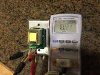
OK, another quick and rough measurement of AT10.
Transformer primary is plugged into 120 VAC outlet via Fluke multimeter set to measure AC current through 300 mA port. The current draw is 10.5 mA. Accordingly, the impedance is ~12K, which corresponds to inductance of 33 H. You could try it yourself, it is pretty easy.
Inductance is strongly affected by frequency and AC voltage, hence the discrepancy between different measurements. What measures 6 H at 1000 Hz (a typical frequency of LCR meters), could easily be 50-60 H at 20 Hz. When I previously reported 70 H, that was at 6 VAC 60 Hz.
There are two components in frequency-dependent change in inductance, one magnetic permeability change and the other change that applies to all coils, regardless of whether or not they have ferromagnetic core.
Attachments
When you see the tag "Camel" on elephant's cage, don't believe your eyes 😀
Sure. As I said, free lunch poor mice can find only in a mousetrap. 😀
XL=j*2*Pi*F*L, and it is complex, i.e. phase shifted in respect to the voltage. Smart meters just know trigonometry and use it to calculate and show numbers on the display. ;-)
Last edited:
Sure. As I said, free lunch poor mice can find only in a mousetrap. 😀
XL=j*2*Pi*F*L, and it is complex, i.e. phase shifted in respect to the voltage. Smart meters just know trigonometry and use it to calculate and show numbers on the display. ;-)
Yes, but "j" (square root of -1) is just to show that inductor's resistance is "imaginary". XL=2piFL formula is used for practical calculations.
- Status
- Not open for further replies.
- Home
- Amplifiers
- Tubes / Valves
- 70v distribution transformer for OPT