In my experiments the not all 0-120-240 transformers are actually centre tapped. The last one I tested for this purpose was 30 ohm 0-120 and 50 ohm 120-240 creating a nasty misbalance. I suggest specifically looking for ones with dual primary.
The further the winding from the core, the longer the copper wire it takes to complete a loop resulting in higher resistance. I don't think measuring the resistance is the best way to determine how "centered" the tap is.
The further the winding from the core, the longer the copper wire it takes to complete a loop resulting in higher resistance. I don't think measuring the resistance is the best way to determine how "centered" the tap is.
Except on a transformer designed to be centre tapped it's always within a couple of ohms.
A 0-120-240 primary is designed to be run as a half or full coil, unlike a centre tap which is always designed to carry the same currents on both halves of the coil.
For modelling purposes has anyone measured the primary L of a 70V or 100V tranny? Estimate
I did one time and it was really low, like mH low.
I have used the Atlas Sound HT87 as a p-p OPT with good results. They are somewhat expensive unless you can get a deal on them. I got a case off ebay for a very good price - about $4 each.
On all the line xfmrs I've used, I've found the "center tap" is two taps down from the tap in use.
This is one I'm wanting to try; just haven't gotten around to buying any. Bogen T-725
Dave's Homemade Radio ~ Bogen T725 Technical Data
On all the line xfmrs I've used, I've found the "center tap" is two taps down from the tap in use.
This is one I'm wanting to try; just haven't gotten around to buying any. Bogen T-725
Dave's Homemade Radio ~ Bogen T725 Technical Data
For 'universal' power transformers, such as commonly found for halogen lighting, the primary windings eg. 0-120-240, are usually provided as 0-120 and 0-120. Yes there can be quite a DC resistance difference between windings, but the turns on each winding are the same.Except on a transformer designed to be centre tapped it's always within a couple of ohms.
A 0-120-240 primary is designed to be run as a half or full coil, unlike a centre tap which is always designed to carry the same currents on both halves of the coil.
For 70V and 100V line transformers that luckily have a mid tapping that is half the turns of the total primary, then again they will typically have a large dc resistance difference between winding halves - that is noted a few times in the earlier links to other projects/details.
In a PP output stage, especially for pentode mode, the AC source impedance of the valve (plate impedance) is much much higher than the dc winding resistance, and so there is negligible mismatch for signal transfer. Also, there is only a minor DC idle voltage difference. So the DC resistance imbalance between the winding halves has no concern. The application is also not highest end hi-fi - and for guitar amps, any minor imbalance could be a benefit.
Last edited:
For modelling purposes has anyone measured the primary L of a 70V or 100V tranny? Estimate?
mike
The OEP D29A100 manufacturer specifications are: primary inductance 3.81H , secondary inductance 6.5 mH measured at 1 KHz, 0.27V.
That's not too bad, Edcor XSE15-8-5K is specified at 3H primary inductance.
The suggestion about the 120+120/12V transformer is great, I just found on my spare box a few high-grade 30VA encapsulated transformers
(from industrial power supplies) that have dual 110V primary and dual 12V secondary windings. I will surely give them a try for less demanding applications, maybe a small 60FX5 "spud" amplifier. Unfortunately there are no halogen transformers here with dual 120V primary. At the office we discarded literarily half a ton of 12V toroidal transformers while upgrading to LED lightning, but they all had a single 220V primary.
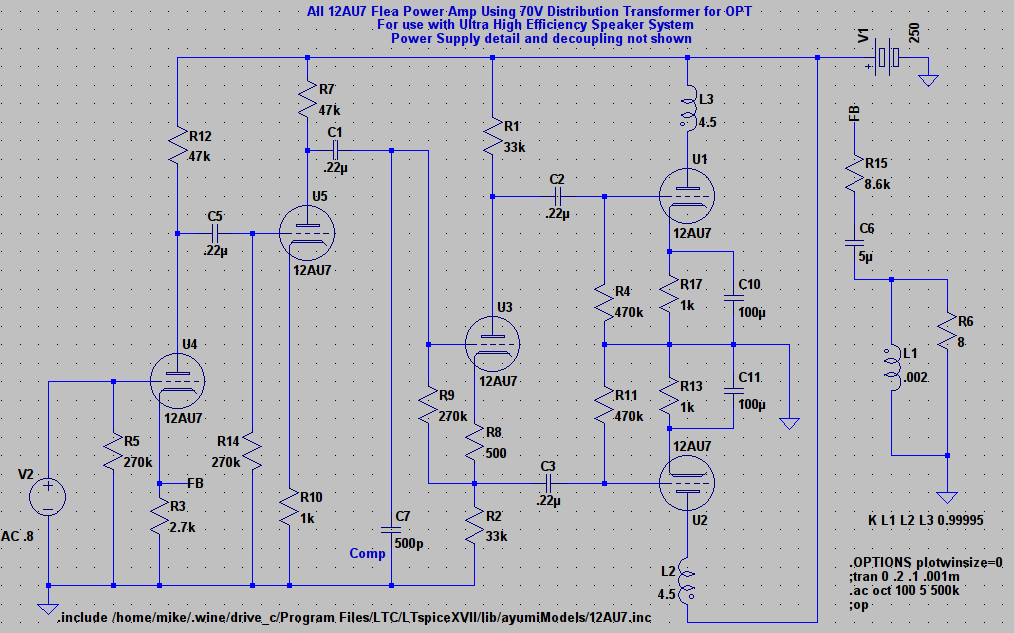
Many thanks. All this input has been very useful. This is the kind of application I had in mind (note this sim is far from complete in detailed component values and PS and is provided only to give an idea of the kind of application).
It would be used to drive very efficient speakers that would be supplemented with a sub. Another possible use would be a multi amp system for mid or tweeter.
It would be used to drive very efficient speakers that would be supplemented with a sub. Another possible use would be a multi amp system for mid or tweeter.
Attachments
Do you really need that much voltage gain to drive these »power« tubes sufficiently? The first triode, U5, could be omitted, the NFB related to U5's cathode instead *imho*. There's also no need for C6, unless you want some certain bass boost.
Best regards!
Best regards!
The OEP D29A100 manufacturer specifications are: primary inductance 3.81H , secondary inductance 6.5 mH measured at 1 KHz, 0.27V.
That's not too bad, Edcor XSE15-8-5K is specified at 3H primary inductance.
The suggestion about the 120+120/12V transformer is great, I just found on my spare box a few high-grade 30VA encapsulated transformers
(from industrial power supplies) that have dual 110V primary and dual 12V secondary windings. I will surely give them a try for less demanding applications, maybe a small 60FX5 "spud" amplifier. Unfortunately there are no halogen transformers here with dual 120V primary. At the office we discarded literarily half a ton of 12V toroidal transformers while upgrading to LED lightning, but they all had a single 220V primary.
My experience has been that any form of EI power transformer has far to high an interwinding capacitance and leakage inductance to be useful as an OT. The encapulated ones are considerably worse since the epoxy has far worse dialetric properties than air.
The only power transformers which can deliver a good (very good) response are toroidals.
Shoog
Do you really need that much voltage gain to drive these »power« tubes sufficiently? The first triode, U5, could be omitted, the NFB related to U5's cathode instead *imho*. There's also no need for C6, unless you want some certain bass boost.
Best regards!
Will look at using only one VAS. It seemed like a single low mu VAS stage would not have enough excess gain for GNF (it worked fine for 0NF though).
I thought the cap in the feedback loop was needed for proper DC biasbeing that the OPT is at DC ground. Certainly would be nice to be rid of it.
For modelling purposes has anyone measured the primary L of a 70V or 100V tranny? Estimate?
mike
measured several of these 100v 10W: http://www.produktinfo.conrad.com/d...9/516104-da-01-en-TONFREQUENZ_UEBERTRAGER.pdf
full primary plate-plate: 9H, 470ohm
full secondary: 10mH, 1.2ohm
primary with secondary shorted: 90mH
if you connect like Ketje one half primary is 75 turns short ...
Last edited:
Well Kay P., you appear to be correct (no surprise 🙂). This seems to give full output of around 1.5W with an input of 1.7V RMS.

Modern power transformers are sectioned for higher loss inductance, to filter out higher frequency dirt. That means HF response of your amp would not be good.
Trannies such as these are what I have in mind.
Quam TCH70 10W-70V Low-Loss Extended LF Speaker Line Matching Transformer
70V 15W Speaker Line Matching Transformer
Quam TBLU 5W-25/70V Speaker Line Matching Transformer Multi-Tap
Quam TCH70 10W-70V Low-Loss Extended LF Speaker Line Matching Transformer
70V 15W Speaker Line Matching Transformer
Quam TBLU 5W-25/70V Speaker Line Matching Transformer Multi-Tap
> really need that much voltage gain to drive these »power« tubes sufficiently?
12AU7 as power tube may need 12V drive.
U5 would have gain of 13, except Rk is not bypassed, so gain of 6.
2V at that grid would work _if_ no NFB were desired.
As NFB seems to be in the plan, another gain of 2-20 is needed to make NFB work. Hence U4.
Yes, could replace U4+U5 with a single higher-gain device. 12AX7 gain of 60 (into cathodyne), 0.2V naked so a 1V sensitivity allows 14dB NFB. Some people dislike 12AX7.
> cap in the feedback loop was needed for proper DC bias
No. Figure your DC bias as R3||R15. Won't hurt to put part of U4 current through the OT. (Yes, ~~1/10th of U4's R15 current then flows in speaker; this should do no harm.)
2.7K||8.6K= 2.05K. This does seem low for 12AU7 with 47K plate load. Well, not that low. And U4 bias does not have to be "optimum" because it only has to swing the small level that U5 grid can take. And running rich increases gain, which is really U4's main job. FWIW, GE R-C data suggests for driving 240K load (you have 270K), use Rp=100K and Rk near 4400r. Since this is twice what you have now (with C6 strapped-out), double R3 and R15. 5.8K and 18.5K (5.6K and 18K, 6.2K and 20K).
The plan has _four_ stages on one power node. Remember the B+ line couples signal at any one stage into any/all other stages. While B+ filtering reduces this (and SPICE's perfect batteries won't allow this), high-gain amplifier chains DO oscillate. Typically the forward bass gain exceeds the backward B+ bass filtering and it motorboats. Rule-of-thumb says no more than two stages per node without hard thinking. While U1 U2 nominally cancel, do not bet on it. Also because U1 U2 mostly do cancel, they do not need super-clean power. But U4 sure needs clean power. U5 and U3 could use judo to improve PSRR, but can't be assumed to do so. And with sane Rp values current in the first few stages would be very low, easy to filter just that. Or with low-cost electrolytic B+ filters, take all 7mA with a 70V drop (250V-180V), 10K, and even 50uFd would be ample. So use 2K and 250uFd to keep first-stages B+ high.
Have you run your sims down to sub-Hz? This is where a many-RC and OT amplifier under NFB often turns vicious, big sub-sonic hump. Maybe you do not have enough NFB gain to be in deep trouble. Remember the OT inductance is very variable with brand and signal.
Last edited:
Trannies such as these are what I have in mind.
Quam TCH70 10W-70V Low-Loss Extended LF Speaker Line Matching Transformer
70V 15W Speaker Line Matching Transformer
Quam TBLU 5W-25/70V Speaker Line Matching Transformer Multi-Tap
I think you will have to just get some and try them out in your application.
I am using the typically small 70 volt OPT's, that Radio Shack used to sell, as replacement OPTS in one of the AES 11BM8 push pull amplifiers that I keep out on my deck.
The little Rad Shack tranny has spectacular frequency response for a small transformer, somewhat low efficiency, terrible square wave response, and fairly shabby two tone IMD characteristics even on matched tubes. It sounds OK though, so I just left them in the amp.
In the same amp, the much heavier ( and more expensive ) Atlas Sound HT 87 has good frequency response, good efficiency, good square wave response, and good two tone IMD characteristics - provided the tubes are well matched. Like the Rad Shack, it doesn't do well on unmatched tubes. I suspect that will be a characteristic of all the line transformers, since they are not made for that. For $1 and $4 / each, respectively, I'm not complaining.
I've used the HT 87 in other homebrew projects and it worked well. Both of these trannies seem to handle 250 ish volts at the currents you would get in a small PP amp.
For pp 12AU7, you probably want one that is pretty efficient.
Win W5JAG
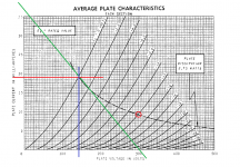
Since the amp is running class A, and the line transformer does not give 1:1 ratio in the primary, it might be advantageous to measure the turns ratio and adjust the output tube current to match ampere-turns values to cancel and thus minimize distortion.
The Quam TBLU could be connected to yield a 16KCT primary, which looks practical for PP 12AU7s in class A1. With the anodes at 300V, I reckon power output of 0.75W for this alignment. Somebody should check my work, though. See attachment.
This tube can deliver a lot more power when the grids are driven positive -- maybe 4W into 16K with +10V grid peaks in class AB2, which requires about 10mA grid drive current. The little Quam xfmr might not like this alignment, however.
This tube can deliver a lot more power when the grids are driven positive -- maybe 4W into 16K with +10V grid peaks in class AB2, which requires about 10mA grid drive current. The little Quam xfmr might not like this alignment, however.
Attachments
Not much inductance in those things so you will need to drive it with a very low Z.
Not much inductance? I measured two such transformers. One, the smaller, was 70H, the other 50H. These were 70V autoformers with taps used as attenuating and impedance matching transformers.
bass is comprimised, frequency response @ 10w = 55 - 20000 Hz
transformer will go much higher but iphone generator tops out at 20khz.
100 - 20khz may do 20w
** BTW this frequency response is perfect for good full range drivers **
So as previously stated, use a sub for the low end
transformer will go much higher but iphone generator tops out at 20khz.
100 - 20khz may do 20w
** BTW this frequency response is perfect for good full range drivers **
So as previously stated, use a sub for the low end
- Status
- Not open for further replies.
- Home
- Amplifiers
- Tubes / Valves
- 70v distribution transformer for OPT