So I thought I would start a thread on my journey to projection bliss. All I have right now is the Innovatek 7" LCD. I must say it has a very nice picture. Here are some photos....
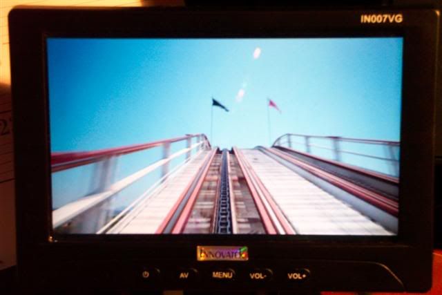
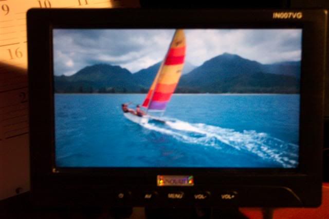
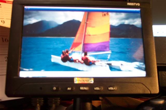
I can assure you that actual image is much much sharper.
As for the other parts to my projector, I am waiting for the Fujion Copy lens 240mm to arrive as well as the 250w light kit from diypojectorcompany. Also waiting to hear back from ace about how much shipping would be from spain to the US(not much I hope 🙁) for the rest of my parts.
I'm still a bit confused on how you are suppose to know exactly how far away the reflector, condensor, fresnels, and LCD are suppose to be from each other. If anyone could provide a link to explain it, that would be great.
Hey skiguy411, well I’m not too sure my self about eh distances, but I think the focal length is what it is, and the distance as to do with each piece, from what I understand it goes like this:
light to condenser: about an inch or two, not too close to touch or get over heated, but close enough to get all the light possible.
condenser to fresnel: the Fl of the condenser is usually close, its where the light hits a pin point and you want the distance of the fresnel to be far enough away but close enough to where its totally covered in light, may need to do some mock up and testing to find this out.
fresnel to LCD to fresnel: you basically just sandwiching from what I understand, the fresnel just straitens out the light and pushes thought the LCD and the 2nd fresnel has its own FL and refocuses the light back down to a pin point
fresnel to lens: I think, not sure but i think the FL of the 2nd fresnel is the distance to the lens, not too sure,
i plan on making mounts for each piece and then spacing them separately to get the best result.
Also not but a few minutes before checking out this post, I posted up how to take apart the Innovatek 7” LCD panel
http://www.diyaudio.com/forums/showthread.php?postid=586345#post586345
Can anyone confirm that? I thought there was some program out there that told you the exact distances everything needed to be?
Also, I'm wondering if I should do a split fresnel design or a single one.
Here are the the specifics about the parts I would like to get from Ace.
The fresnels : 210 bottom focal and 310 top focal.
Reflector : Spherical 32.6mm focal
Condenser: 80mm diam, 89mm focal
As for IR and UV filtering, I plan on getting some lexan from Home depot(if they have it) for UV. Im hoping the 120mm fans by the the light along with maybe an 80mm blowing on the lcd will be enough to keep the heat down.
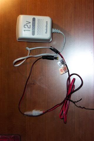
Here is how I did the power for the LCD. Posted this in another thread, but thought I would put it here for future reference. Basically I just cut the radio shack connector off and soldered the power connector included with the LCD.
Probably going to order the parts from Ace today. However, I am concerned with the cut fresnel size and the Innovatek LCD size. Can anyone confirm that the Lilliput and the Innovatek are using the same LCD panel? Or at least the same size?
By the way shipping from Spain to the US is $30 🙁
By the way shipping from Spain to the US is $30 🙁
Another question for you guys. Feel free to answer any of my questions above as well.
Does the mirror that reflects the light from the bulb to the LCD need to be a FS mirror or will any mirror due?
Does the mirror that reflects the light from the bulb to the LCD need to be a FS mirror or will any mirror due?
im pretty sure it doesnt matter if its a front furface or not for the mirror which reflects the light from the bulb to the lcd.
One thing which is good to do though would be to use a cold mirror (which would prob be front surface anyway). The cold mirror would reflect visible light but would allow Infra-red (heat) to pass through meaning your LCD and fresnels wont get so hot.
im not sure what size mirror you would need to reflect light with a 7inch screen but surplusshed.com sell them very cheap. I dont know if this would be the right size or big enough.
Ok, So diyprojectorcompany doesnt have the 250w light kit in stock....
Does anyone know where I can get something like it/better here in the U.S. for about the same price?
Does anyone know where I can get something like it/better here in the U.S. for about the same price?
BAH!
I tried to strip the LCD today. I got it all apart, plugged it in and it worked. So I decided I would set up a small test bed. When I went to plug it in again, I got nothing. So I put everything back together and turned it on and all I got was a white blank screen.
I am so pissed off at myself. Please tell me there is something I can do/check.

Could have been a static discharge. Were you properly grounded?
Sometimes certain PCBs may need a common ground. Does your monitor have any wires that were attached to the monitor frame? Sometimes the PCB mounting holes themselves are used as grounds.
At least some ideas to think about...
Best of luck
Sometimes certain PCBs may need a common ground. Does your monitor have any wires that were attached to the monitor frame? Sometimes the PCB mounting holes themselves are used as grounds.
At least some ideas to think about...
Best of luck
Well I didnt have a wrist strap on, but I did touch the metal around the outside before touching the board.
I dont think there are ground wires. The LCD is basically the same as the Lilliput.
Did I just flush $200 down the toliet?
I dont think there are ground wires. The LCD is basically the same as the Lilliput.
Did I just flush $200 down the toliet?
Ok after doing some more testing, it looks like it may be ESD. I used the multimeter to see if there was any current flowing from the white FCC, which there was. I then used the multimeter to see if there was any current on the other side(where the brown FCC connects). There was none.
Does this seem logical that since there is no current on the side where the brown FCC connects that controller card is what is broken? Is it possible to buy just the small controller card?
Does this seem logical that since there is no current on the side where the brown FCC connects that controller card is what is broken? Is it possible to buy just the small controller card?
The little board needs to be at a 90 or 180o angle like it is when its inside its housing or no connection is made 🙂 now be careful and dont fiddle with it to much or u will snap a wire i sugest you make a frame for it and leave it in it
VERY IMPORTANT THIS IS! TRUST ME
VERY IMPORTANT THIS IS! TRUST ME
Thanks for your reply nick.
I have tried putting it all back together with back light and everything behind it and screwed the small card in. Still no success 🙁
Any other suggestions?
I have tried putting it all back together with back light and everything behind it and screwed the small card in. Still no success 🙁
Any other suggestions?
Yeah, I have tried the FCC cable every way it could go. I have taken it apart and put it back together at least 5 times and checked every connnection.
Is there suppose to be voltage on brown FCC side?
Is there suppose to be voltage on brown FCC side?
Hmm, its possible you have broke a connection, if you have broke a connection on the brown fcc cables then your ****** basicly will cost you about $75-$100 US for a new lcd panel if you can get hold of one (took me about a month to find one)
When i first got my panel i got a white screen because the 4pin fcc cables wasent in enouth
When i first got my panel i got a white screen because the 4pin fcc cables wasent in enouth
- Status
- Not open for further replies.
- Home
- General Interest
- Everything Else
- The Moving Image
- DIY Projectors
- 7" Innovatek Projector (based on Hillbilly's design)