RE: Post # 9.
Putting a capacitor across a gas regulator tube may not be a good idea.
In regulated PS design it was fairly common to find something up to 0.1 microF across a gas regulator. Helps to remove any noise generated by the gas tube. Too much capacitor across a gas tube often results in a pretty goad oscillator!
Some may have taken my comment regarding hooking up a scope to the subject amp as an indication I'm not in favor of SE. But over many years I've built several, mostly SEP & all with NFB. They have all performed well, you could say somewhat better than 'good enough' for the application they were built for.
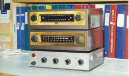
The attachment is one of these amps, a FB Pair in the output of 6AU6 & 6AQ5. This one built in 1968 & used every day in my workshop with Eico AM & FM Tuners. It has a built in magnetic phono stage as well.🙂
Found this link with many SE amps similar to the original amp in this thread-
http://www.single-ended.com/EL156amp.htm
Attachments
An OD3 150V gas regulator has about 114 Ohms dynamic resistance.
A 0.1 uF cap is about 80 Ohms at 20kHz.
That will give approximately 3 dB noise reduction at 20kHz.
(and I do not hear anything above 15kHz).
A 0.1 uF cap is about 800 Ohms at 2kHz.
There will be very little noise reduction at 2kHz.
Will anybody even notice?
Is it even worth putting a 0.1uF cap across the OD3?
One more part, one more expense, one more part to fail, two more possible bad solder connections, one more part to find space to put it.
Anybody care to do some measurements, and see how good or bad the noise is?
WikiPedia on Gas Regulators
See reference to noise under Design Considerations.🙂
Voltage-regulator tube - Wikipedia
See reference to noise under Design Considerations.🙂
Voltage-regulator tube - Wikipedia
Some may have taken my comment regarding hooking up a scope to the subject amp as an indication I'm not in favor of SE. But over many years I've built several, mostly SEP & all with NFB. They have all performed well, you could say somewhat better than 'good enough' for the application they were built for.
The attachment is one of these amps, a FB Pair in the output of 6AU6 & 6AQ5. This one built in 1968 & used every day in my workshop with Eico AM & FM Tuners. It has a built in magnetic phono stage as well.🙂
Found this link with many SE amps similar to the original amp in this thread-
http://www.single-ended.com/EL156amp.htm
I would say "very well" what you need to listen naturally to the character of the single valve, with its strengths and weaknesses ... certainly not to let it express its full potential.
I don't know the sound of the 6AQ5 ... it was a tube very used also here in Italy before the advent of the 6BQ5.
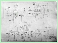
Looking at the power section schematic of the 3W jhstewart9 amplifier, I have a few questions:
- What is the purpose of C3=150pf across the 6AU6 anode resistor?
- why the 6AU6 grid leak resistor value is so high (R2 = 5.6 M)?
- 14V at the 270 ohm cathode resistor means 50mA cathode current. The tube is dissipating 13.5W at zero signal input. According to GE datasheet, the design center maximum plate dissipation is 12W and G2 dissipation is 2W, so the tube is running right at the edge. Is the output tube life still acceptable?
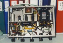
- I like this late '60 build style, the tubes horizontally mounted inside the low-profile chassis, but on devices of this era I often see an asbestos sheet glued to the inside of the top cover to lower the external cover temperature, or a metal termal shield bolted to the chassis and spaced about 5mm from the cover. On the audio xpress article there is little mention of the internal mechanical arrangement; is a picture available?
It looks to be a whorty design to build. Putting all those features in such a small chassis is definitely a big achievement, but I plan to build the power section only, so it should be a manageable task.
- What is the purpose of C3=150pf across the 6AU6 anode resistor?
- why the 6AU6 grid leak resistor value is so high (R2 = 5.6 M)?
- 14V at the 270 ohm cathode resistor means 50mA cathode current. The tube is dissipating 13.5W at zero signal input. According to GE datasheet, the design center maximum plate dissipation is 12W and G2 dissipation is 2W, so the tube is running right at the edge. Is the output tube life still acceptable?
- I like this late '60 build style, the tubes horizontally mounted inside the low-profile chassis, but on devices of this era I often see an asbestos sheet glued to the inside of the top cover to lower the external cover temperature, or a metal termal shield bolted to the chassis and spaced about 5mm from the cover. On the audio xpress article there is little mention of the internal mechanical arrangement; is a picture available?
It looks to be a whorty design to build. Putting all those features in such a small chassis is definitely a big achievement, but I plan to build the power section only, so it should be a manageable task.
Doing the Numbers
A quick calculation looks like the 6AQ5 is running over the limit. But stuffing the numbers from the schematic into the HP67 & turning the crank I get the following-
14V across 270R looks like 52 ma. But some of that is G2 current.
15V drop across L1 the 20H choke, 1667R (Hammond Spec) is 9 mA
35V drop across R9 (22K) is 1.6 mA
135V drop across R10 (180K) is 0.75 mA
So G2 current is 6.65 mA
And 6AQ5 plate current is 45 mA.
Total plate volts is 285 - 14(Rk) - 14(T1)........257V
Total Plate watts is 257*0.045 = 11.57
Close to the 12W limit.
But the amp has run without problems for a very long time. These tubes would all be from production when the best tubes were being built in very large quantities. So reliability is very good. I recall replacing the 6AQ5 only twice since the amp was built, the other tubes never.🙂
Attachments
It is too bad that Wiki article did not say how much noise reduction there would be,
when using a 0.1uf cap across the gas regulator tube.
It also did not even mention the noise reduction versus frequency.
White noise, Pink noise, 1/f noise. Lacking in information.
when using a 0.1uf cap across the gas regulator tube.
It also did not even mention the noise reduction versus frequency.
White noise, Pink noise, 1/f noise. Lacking in information.
Some info regarding noise but no measurements.
See notes.
https://tubedata.altanatubes.com.br/sheets/035/0/0E3.pdf
https://tubedata.altanatubes.com.br/sheets/030/8/85A1.pdf
https://tubedata.altanatubes.com.br/sheets/138/0/0B2WA.pdf
https://tubedata.altanatubes.com.br/sheets/084/0/0B2.pdf
https://tubedata.altanatubes.com.br/sheets/084/0/0A2WA.pdf
https://tubedata.altanatubes.com.br/sheets/030/0/0A2WA.pdf
Seems a 0.1uF in // has no interest for audio purpose..?
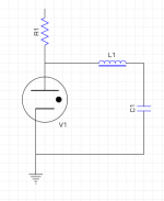
emk₂;6190890 said:should work? or oscillator 😕
Yah, that works.
Real-world chokes (even air-core ones) have resistance losses. For instance, I have long been a fan of using 10 kΩ, 2 watt resistors as the 'winding form' for some № 42 gauge wire, to build pretty decent small current 'air core' inductors.
Using a Dremel™ tool, and a cloth 'holder' for the other wire-end of the resistor, one can spin 2,000 turns in perhaps 15 seconds. First time is a disaster, but when you get used to it, its pretty easy. In a jiffy, on Ohmite 2 W resistors, you have an 800 µH inductor, for basically 10¢ or less.
Wire resistance, 200 Ω. In parallel with 10 kΩ … is still 200 Ω. LOL. And one just uses a blue-flame alcohol 'lamp' to burn off the insulation. Solder directly to the leads. Voilá. Strictly, you don't need much of a capacitor either.
In any case, VR tubes make fine voltage references with a little filtering. On the other hand, so do Zeners. Especially those manufactured to have VZ around 4.5 volts or so … the 'zero temperature coefficient' sweet spot. One can make a pretty solid precision constant current source with them, which in turn with well-temperature-compensated higher value resistors results in a fairly well-compensated precision higher voltage source … of almost any value.
⋅-⋅-⋅ Just saying, ⋅-⋅-⋅
⋅-=≡ GoatGuy ✓ ≡=-⋅
Using a Dremel™ tool, and a cloth 'holder' for the other wire-end of the resistor, one can spin 2,000 turns in perhaps 15 seconds. First time is a disaster, but when you get used to it, its pretty easy. In a jiffy, on Ohmite 2 W resistors, you have an 800 µH inductor, for basically 10¢ or less.
Real DIY! 🙂
A string of four 56V 5W zeners worked well for a basic g2 regulation of a 829PP. Unfortunately, it doesn't glow..
https://tubedata.altanatubes.com.br/sheets/030/8/85A2.pdf
Maybe a good choice for low current.
Attachments
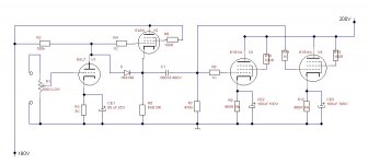
In the end this is the almost definitive schematics that I am redoing ... the only doubt that remains concerns the NFB ring ... do you have any advice to give me, whether to leave it as it is, whether to increase the R8, or whether to eliminate it all?
Attachments
In the end this is the almost definitive schematics that I am redoing ... the only doubt that remains concerns the NFB ring ... do you have any advice to give me, whether to leave it as it is, whether to increase the R8, or whether to eliminate it all?
Looks OK. 6SL7 Gain is ~ 40, 6Y6 Gain is ~ 21.3, OPT is 0.0516. So Open Loop Gain is ~44. NFB will set the amp gain to 7.8, so NFB is ~15 db, a good, conservative number. If you or a friend have a scope & square wave generator your amp could be checked for overshoot on the signal edges. The simplest fix is a small cap across R4. Size depends on the frequency response of the OPT.
Add a 1K, 1/2W Carbon Composition resistor into the lead from the VC to the 6SL7 grid. And a 100R, 1/2W CC resistor in lead to the 6Y6 G2, as close as possible to the tube socket.
The sound will depend most on your speaker & listening environment provided the amp is running properly.🙂
Hello.
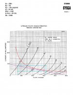
These could be reliable data that could be found in the datasheets, if Vg is assumed to be -28mA.
I hope I haven't made mistakes ...
More accurate data could be provided with Koren.
Attachments
Last edited:
...The attachment is one of these amps, a FB Pair in the output of 6AU6 & 6AQ5. This one built in 1968 & used every day in my workshop with Eico AM & FM Tuners. It has a built in magnetic phono stage as well.🙂
Mr. Stewart, thank you for reminding me of this little amp. I remember reading your article way back when and always wanted to try it. I have thought about using two 6aq5s in parallel on the output. Off the cuff, do you see any issues with that, or will I have to modify your circuit?
I would like to use this opportunity to thank you for all your contributions to DIY tube electronics. I have thoroughly enjoyed your work and writings over many years.
(Apologies to OP for this slight diversion)
Best wishes,
Francois
Last edited:
Mr. Stewart, thank you for reminding me of this little amp. I remember reading your article way back when and always wanted to try it. I have thought about using two 6aq5s in parallel on the output. Off the cuff, do you see any issues with that, or will I have to modify your circuit?
I would like to use this opportunity to thank you for all your contributions to DIY tube electronics. I have thoroughly enjoyed your work and writings over many years.
(Apologies to OP for this slight diversion)
Best wishes,
Francois
In general feedback pairs such as that cct are simple, easy to build & trouble free. As I respond today the amplifier in that article is running in the workshop. It could benefit from a better OPT but for the environment it is used is better than AOK. I expect it will be still running long after I expire.🙂
Make sure the OPT used in your amp is gapped as usually required for an SE amp. And all will progress smoothly for you.🙂
- Home
- Amplifiers
- Tubes / Valves
- 6Y6 SE amplifier