Please use the forum Attach Image function. That OneDrive hosting is a pain.
> capacitance of many tubes in parallel forces special design... can I..?
Figure it out.
6Y6 as Pentode has 12pFd G-K and 0.66pFd G-P. The G-P is multiplied by gain. Without strict analysis, I see that 14V on G covers 200V plate supply, maybe 140V-160V plate swing, so loaded gain is 10-12. So 12pFd to K, 8pFd of Miller, and I'd allow some dozens pFd for "stray". So >20pFd but maybe <50pFd per tube.
Times four is say 100pFd-200pFd.
Note that a bare 12AX7 gain-stage tends to 100pFd input. (1.7pFd times Gv=50.)
So a quad of 6Y6 is not much worse than one 12AX7. I would not fret.
200pFd at 20KHz is about 42K reactance. Can your driver manage 42K? We know it must do 125K (max Rg1 for 6Y6 is 0.5Meg). Actually load is near 125K||42K= 31K.
Cathode follower is useful to control small-signal roll-off but will NOT drive high-level better than the same tube at the same current working for gain.
At 20KHz we need 14V peak in ~~31K, or a half mA. Without hard thought, we can probably just be generous, run the driver at 5mA. This leads to a 12AU7, a fine little tube when you need grunt. Get gain of 10-15, if you need it. Rp at 5mA is near 6K, so flat to >100KHz driving 200pFd.
> cannot find examples of SE amps with NFB
There's tons. A marginal example is Fender AA Champ. The values picked to tune a cheap guitar speaker for a cheap amp don't do a lot, but the topology is valid. Drop the 2.7K NFB resistor to 1K or less for high NFB.
If you going to use the H-K version, then the gain is insufficient. OTOH, Max Robinson's modified version has a loss of just 6 dB, which might just be enough.
Taking NFB around a tone control ideally makes the tone control no-effect.
There's well-trod paths that just work. Don't try to hack your way through the jungle, swinging wildly. Plagiarize. Study all the circuits you can find.
There's well-trod paths that just work. Don't try to hack your way through the jungle, swinging wildly. Plagiarize. Study all the circuits you can find.
How about Max Robinson's "A tone control you can love" (Fig 14)Max Robinson's modified version has a loss of just 6 dB
Practical Tone Controls.
This could be followed by the volume control, and then the amp?
I am quite willing to plagiarize, and do study the circuits, but I am a mechanical engineer and do not always understand what I am studying. As each of you make observations I enjoy revelations of "oh, that is what these circuits were telling me"!Plagiarize. Study all the circuits you can find
> a mechanical engineer and do not always understand what I am studying.
You were not born knowing rivet stresses(*), moment diagrams, modulus of elasticity. Any new field needs lots of brain-hammering, and keeping non-understood info around until other info frames a context.
You have seen NFB, and you have seen tone controls. And yes, audio is full of bull and you WILL find tone-nets inside NFB loops (notably in guitar amps, where many silly things are cool). You are yet to integrate why a "straight" (not overdriven) music amplifier won't normally have tone-net inside the NFB loop. I predict this will "ah-ha!" soon.
(* I guess they don't teach rivets any more?)
If you really want to use tone controls with NFB, then you can add a recovery, buffer stage between the tone control and the power tubes. The NFB can be returned to said stage, look at some old schematics, there are many examples.
Any idea what his B+ was?Max Robinson's modified version has a loss of just 6 dB, which might just be enough.
Attachments
the resistor values were far from those in the 12AX7 data sheet, but I guess he was targeting lower gain than any of the datasheet examples.
His other examples utilized a B+ of 250V and I had planned to use 250V, so I had hoped to duplicate component values, but without correlation to a another 250V example with components in the same region I feared that my assumption could become a problem.
His other examples utilized a B+ of 250V and I had planned to use 250V, so I had hoped to duplicate component values, but without correlation to a another 250V example with components in the same region I feared that my assumption could become a problem.
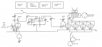
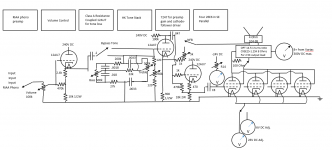
I just figured out the 7247 tubes I inherited from my Father-in-law.
They seem perfect to insert between the tone stack and the output tubes, the 12AX7 half for gain, and the 12AU7 half for cathode-follower driver.
Did I get it right? If so I will finish the circuit...
They seem perfect to insert between the tone stack and the output tubes, the 12AX7 half for gain, and the 12AU7 half for cathode-follower driver.
Did I get it right? If so I will finish the circuit...
Attachments
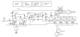
I would make the Volume pot smaller, say 100k, also get rid of C1 unless you really need it. You are also missing the plate resistor on the recovery stage, and having an extra coupling capacitor to the CF. If the HF response and the drive voltage is good enough from the recovery stage, then you can skip the CF - you can test it out pretty quicky on the breadboard.
I see you change the schematic completely... Again, I would encourage you to look at some schematics from HK, Marantz, HH Scott, etc., to see how the gain blocks, volume control, and tone controls are arranged.
Yes, I am struggling with the tone control!
The Marantz models 2, 5, 8, and 9 insert tone control immediately prior to the output tubes, and bypass the tone control with NFB
The HK models 224, 230, 250, and 700 move the tone control earlier in the circuit, before phase split and drive, and they delete NFB
The Scott models 72, 210, 222, 299, and 488 position tone like the HK, but move volume control to follow tone control
Some Zeniths place both volume and tone prior to the first tube
Unfortunately none of them provide a bypass switch to eliminate the mess!
So I thought that I was plagiarizing HK with only one gain block prior to tone control. Although I had truncated NFB to follow tone control on advice of forum members, and was trying to add a bypass for tone
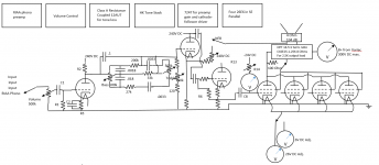
Since you will have a RIAA stage before the preamp, it makes more sense to put the volume control after the tone control, and if you make the first stage of the preamp have a gain that equals the loss of the tone control, then you can simply bypass both with a switch, while still retaining the gain needed to drive the power tubes.
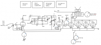
I am now using the Max Robinson enhancement of the HK tone which uses a 12AX7 with gain of 10 to comp. the 20dB loss, and a bypass for both.
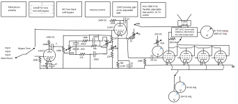
However I also show a 2nd circuit in which I replaced Max's 12AX7 with a 12AU7. To me it is more intuitive to achieve the low gain with the AU, and I do not understand how he is achieving the low gain with the AX.
However I also show a 2nd circuit in which I replaced Max's 12AX7 with a 12AU7. To me it is more intuitive to achieve the low gain with the AU, and I do not understand how he is achieving the low gain with the AX.
Attachments

- Status
- Not open for further replies.
- Home
- Amplifiers
- Tubes / Valves
- 6Y6/26E6 PSE Amplifer