Some load lines for your consideration
While on the subject of datasheets presenting an oversimplified snapshot...
The 6Y6 data sheet suggests a 2.6k Ohm loadline and grid bias of -14V @ 200 Plate V
The curve for consideration suggests a 3.4k Ohm loadline with -28V bias @ 200V plate?
What drives the higher load and bias?
Remember that those values are for wired as pentode.
I still prefer to look at the OLD data published in the original datasheets, if data is available:
https://frank.pocnet.net/sheets/137/6/6Y6GA.pdf
Scroll down to the 3rd page to see published average plate curves for triode connection.
I still prefer to look at the OLD data published in the original datasheets, if data is available:
https://frank.pocnet.net/sheets/137/6/6Y6GA.pdf
Scroll down to the 3rd page to see published average plate curves for triode connection.
Most data sheets include at least one example of operating conditions where plate V equals screen V. Do those conditions reasonably approximate UL operation?
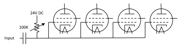
The 6V6 likes twice the output resistance of the 6Y6, so can I size my OPT for four 6Y6 tubes in parallel and "roll" to two 6V6 tubes with two sockets vacant?
The bias will need to be adjusted, but screen resistances seem to fall in the range of 35k to 50k Ohms, so a 24V supply with a 100k pot in series should allow me to tune bias from about 8 to 24V? In combination with the Variac for B+ I should have great flexibility in rolling tubes...
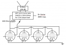
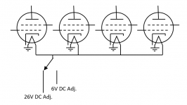
Images of the OPT, bias, and heater circuit
The intent is breadboard flexibility packaged for the living room for the subjective evaluation of tubes, tube and OPT relationship, bias, B+, etc.
My only experience is with cathode bias, so I am uncomfortable with the bias circuit. The bias is supplied by a separate power supply so that it is not influenced by adjustment of B+. It would have a dedicated voltmeter and access to the pot for easy adjustment.
The Variac would also have a dedicated voltmeter for easy adjustment without opening the chassis.
Attachments
The grid voltage has to be negative and you have to turn the bias down a bit so the max current of the OPT is not exceeded (200mA).
I just connect the + terminal of my 24V supply to ground, right?
For some reason the CXSE25-1.25K is rated for 250mA even though the other transformers in the series are rated for 200 mA. In any case I will be near the edge of its rating and may need to bias for lower power as you suggest.
Are there other transformers I should consider? I would really love to find something with multiple taps very close together for fine tuning of of the output load! (for example 13:1, 14:1, 15:1 turn ratios)
Yes.I just connect the + terminal of my 24V supply to ground, right?
250mA is better, in any case, you can adjust the bias to suit. But the primary impedance should be 625 instead of 2.5k as shown in your schematic, i.e., 1.25k:8 wired for 625:4.For some reason the CXSE25-1.25K is rated for 250mA even though the other transformers in the series are rated for 200 mA. In any case I will be near the edge of its rating and may need to bias for lower power as you suggest.
You can try Hammond, but for multiple taps, good luck finding one. In any case, closely spaced primary taps aren't really that useful, if anything, get one with multiple secondary taps.Are there other transformers I should consider? I would really love to find something with multiple taps very close together for fine tuning of of the output load! (for example 13:1, 14:1, 15:1 turn ratios)
I think my attempt to express the single-tube equivalent load line for the OPT was confusing.But the primary impedance should be 625 instead of 2.5k as shown in your schematic, i.e., 1.25k:8 wired for 625:4.
My logic was:
I want a 2.5k load on the tube with a 4 ohm load on the secondary, so for a single tube I would want 2.5k:4 OPT
With four tubes the OPT would be 625:4
But as this is not available I could use 1.25:8 as it would have the same turns ratio?
Some of the posts on OTL amps note that the capacitance of many tubes in parallel forces special design of the previous stage. Can I ignore this with 4 tubes? Especially with resistance coupled stages?
http://www.tubebooks.org/tubedata/HB-3/Receiving_Tubes_Part_1/Resistance-Coupled_Amplifiers.PDF
http://www.tubebooks.org/tubedata/HB-3/Receiving_Tubes_Part_1/Resistance-Coupled_Amplifiers.PDF
To deal with the Miller capacitance, you can use a cathode follower as the driver, probably a good idea with 4x tubes.
Thanks for introducing me to the cathode follower!
It seems that they are frequently used to drive tone-stacks as well. Should I use two of them, one for the tone-stack and one for the 4 tubes?
It seems that they are frequently used to drive tone-stacks as well. Should I use two of them, one for the tone-stack and one for the 4 tubes?
It depends on what kind of tone control that you plan to use, it might be a good idea to draw up a preliminary schematic to show people what you are working on...
Following are the logical blocks, and then the draft of the schematic...
The power supply is not yet shown (yes I know that the Variac does not provide DC!)
The table of values for R and C are not shown as I have not decided how much gain I need from each stage.
Known errors include the omission of grid stoppers on the drivers, and I am confident that there are many others
It did seem appropriate to collect advice on the approach prior to sorting out the details.
An externally hosted image should be here but it was not working when we last tested it.
An externally hosted image should be here but it was not working when we last tested it.
The power supply is not yet shown (yes I know that the Variac does not provide DC!)
The table of values for R and C are not shown as I have not decided how much gain I need from each stage.
Known errors include the omission of grid stoppers on the drivers, and I am confident that there are many others
It did seem appropriate to collect advice on the approach prior to sorting out the details.
The FMV tonestack isn't really suitable for hi-fi, perhaps you should look at some other options. To calculate the gain required at each stage, you need to work backwards from the output to the input.
The Baxendall shown in Figure 20?
Practical Tone Controls.
This seems to include its own cathode follower, so it would replace both the cathode follower and the tone stack in my draft.
Practical Tone Controls.
This seems to include its own cathode follower, so it would replace both the cathode follower and the tone stack in my draft.
I need something like 20V to drive the 6Y6s, and I expect an input of .45V (see below) , so the total gain of all stages needs to be at least 44?
If I use an active tone control like the Baxendall I have no insertion loss, so I still need a gain of 44. This seems to eliminate the 2nd Class A preamp I show, and both cathode followers.
I was thinking of using the old RCA RIAA circuit below
7025, ECC803S, 12AX7A Tube RIAA Phono Preamplifier Schematic
With a gain of 150 it should take my MM or .003V to .45V for the input to my draft schematic
0.45V is pretty low, especially when used with modern sources, which have much higher outputs. Also, you may need to apply some NFB to get the distortion down and the damping factor up, so the gain requirement may be different, but I guess 44 is as good a place to start as any.
Input from a CD would be around 2V?
Perhaps I should find another RIAA schematic with more gain so the phono input is closer to the modern ones.
But 2V in and 20V out would provide a gain of only 10. This sounds very low, did I miss something.
I cannot find examples of SE amps with NFB. It would comprise a resistor between the secondary taps of the OPT and the input?
Several blogs rant against NFB for SE, while others tolerate it. Should my resistor be an accessible pot for tuning, with a blocking resistor to create a lower resistance limit?
Any alternatives to the Baxendall I should consider?
- Status
- Not open for further replies.
- Home
- Amplifiers
- Tubes / Valves
- 6Y6/26E6 PSE Amplifer