There is a lot of wrong or misleading information here....
Measured power can be input or output in a typical amplifier. It is usually expressed in watts, but there are other valid units.
An RF "transmitting" amplifier, like an audio amplifier takes a small SIGNAL INPUT and amplifies it into a larger OUTPUT SIGNAL that is sent to a speaker or antenna. It consumes electrical POWER INPUT from the power supply to do this. The ratio of OUTPUT POWER applied to the load (speaker or antenna) to POWER INPUT (from the power supply) determines the amplifier's EFFICIENCY. The INPUT POWER consumed by the amplifier and not converted into OUTPUT POWER (input power - output power) is the heat dissipated in the output device (tube or solid state device).
A hypothetical tube amp may consume 10 watts from the power supply, to produce 3 watts of audio. It will then dissipate the other 7 watts as waste heat in the tube. It converts DC power to audio power with an efficiency of 30% which is typical for a good Single Ended amp running at near maximum power output.
A motor is a device which can consume electrical INPUT POWER (usually measured in watts) and convert it into mechanical POWER OUTPUT. It is often measured in HorsePower in the US, but other units are equally valid. Volkswagen often rates their engines in Kilowatts, especially in their European spec cars.....1 HP = 746 watts, they are both valid units for measuring power. So an electric motor that consumes 1 KW input to produce 1 HP output is 74.6% efficient in its conversion. This is lousy for a modern motor.
Electrical power (watts) is a product of the current (amps) and the voltage (volts) in the circuit.
Mechanical power is a product of the torque (ft / lbs in the US) and the RPM divided by a constant (5252 when US units are used).
COMPLETE amplifier measurements whether RF or audio should state the INPUT POWER (from the line or other power source), the available POWER OUTPUT, the gain (how much audio or RF is needed to get the desired or specified audio or RF power at the output), and the distortion characteristics of the amplifier. Different units of measurement and methods are used in the RF world compared to the audio world for distortion, but the principles are the same.
The speaker, or other transducer will convert the electrical power supplied to it by the amplifier into acoustical power. It is a different device with it's own measurement criteria, often not well defined. It is similar to the case of a BLDC motor where an "amplifier" will convert DC power into 3 phase AC power (which could be measured in watts), then apply that power to the mechanical components which will convert that AC power into mechanical rotational power.
I'm assuming power OUTPUT?
UH, no.....
The worse case in a class A amplifier is an amp sitting at idle with no SIGNAL input. The volume is turned down, or the record is done playing and the listener has fallen asleep. In this case the tube (assuming a 6V6) is still drawing power from the power supply, according to how it was biased up when the amp was built or set up. The output power is ZERO because there is no music playing. ALL of the INPUT POWER is burned up in the tube (dissipated) as none is being sent to the amplifier's output. The MAXIMUM DISSIPATION of the plate in a 6V6 is 12 watts, and the screen grid is 2 watts, so the INPUT to the 6V6 could be 14 watts without violating any specs. This is not good design practice for reasonable tube life, so less INPUT POWER than the maximum should be applied in a good design.
The GE data sheet gives "typical operation" specs for a SE amp with a 5K load. It shows 250 volts on the plate with 45 mA drawn at zero signal (idle). That is 11.25 watts INPUT POWER to the plate. The screen grid gets 250 volts and draws 4.5 mA for 1.125 watts of INPUT power. The total INPUT POWER is 12.375 watts, and the OUTPUT POWER is ZERO! The tube is turning ALL of it's INPUT POWER into heat.
Now lets apply a simple sine wave and crank it up until the THD reaches 8%. Here the data sheet gives us 4.5 watts of POWER OUTPUT. The tube is now getting 250 volts on the plate but it draws 47 mA for 11.75 watts INPUT. The screen grid gets 250 volts and draws 7 mA for 1.75 watts INPUT. The total INPUT POWER to the tube is 13.5 watts, BUT 4.5 watts of audio power is being delivered to the load, so the tube dissipation GOES DOWN to 9 watts.
Here the efficiency is 33%. 1/3rd of the POWER INPUT to the tube is converted into audio POWER OUTPUT, and the other 2/3 (9 watts) is turned into waste heat in the tube.
In almost all cases with a single ended amplifier, the maximum POWER OUTPUT is limited by how much POWER INPUT can be applied to the tube with no SIGNAL input to the tube. We can do things to improve the efficiency of the tube, like drive the grid positive (A2 operation), but a best case situation is in the 45% range.
A single ended AUDIO amplifier must run in class A, either A1 (no grid current) or A2 (grid driven positive). A2 works well with some tubes, and poorly with others. As stated, it's not often documented in the tube books.
In the RF world an amplifier may run in class A, AB, B or even class C depending on the distortion performance needed in the design. A signal with no amplitude modulation component like FM can run in hard class C where efficiencies can run in the 80+% range, while complex modulation schemes like LTE require near class A linearity.
The situation becomes more complicated when the amplifier runs two devices in a push pull arrangement where the load is shared. Here class A, AB, and near class B operation can be used for audio, with or without grid current.
As with a single ended amplifier, in class A, worse case is at zero signal input. Tube dissipation is maximum when the amp is idling. POWER OUTPUT is still limited by maximum tube dissipation and the calculations are the same as two SE class A amps running at the same time on the same signal.
The other extreme is pure class B. There is NO dissipation at idle, since the tubes are both biased at cutoff. It will peak at maximum UNDISTORTED power output, and drop as the amp is slammed hard into clipping. Pure class B has distortion problems at low signal levels, so we run class AB, where the bias is set somewhere between class A and Class B. Here the point of maximum dissipation will be somewhere between idle and max power output, depending on the bias current.
A competent amplifier designer must test all possible operating conditions and calculate the plate and grid dissipation levels for each. Peak cathode current must be checked for amplifiers operating at high power levels, or when extracting more than the textbook power levels for any given tube. Here computer simulations are valuable time saver, provided the vacuum tube models are reasonably close to the real tube being used.
I can assure you that with the proper circuit, a pair of 6V6's can crank out 30 watts without issue in class AB2.
I can find no evidence that the 6V6 was ever INTENDED to be a transmitting tube although it was often used as one (as were many surplus pentodes) once they were in plentiful supply.
The original metal 6L6 was intended for audio amplifier use. it was the first "high power" pentode created in large volume, so it got used for nearly everything, and several specialized versions of it were created. The original 6L6 pinout had the plate on pin 3 and the heater on pin 2. This created problems with arcing even in audio amps. The 6L6 "guts" were adapted to RF by moving the plate connection to a top cap, and using a base with wider pin spacing to reduce capacitance.....that became the 807.
The 6L6 guts wound up in two different TV sweep tubes. The big one was the 6BG6, with the plate on a top cap. The smaller flavor was the 6BD5GT, yes a 6L6 plate was squished inside the envelope of a tube the size of a 6V6. They were never very popular since the 6AV5GT and 6AU5GT took over the sweep tube duties within a year or two.
The true 807's are made from 6L6GA guts. There were plenty of "807's" and 1625's made during and after WWII with all sorts of different guts. I have seen some that are missing the RF shielding around the bottom mica, and some with 6L6GC or 7027A guts. These have big wings n the plates and will dissipate 30 watts as compared to the original 19 watt spec.
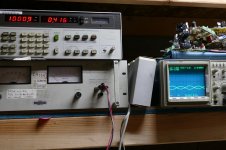
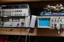
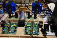
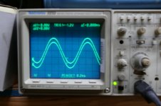
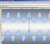
I put a pair of 6L6GA's to the test with a 3300 ohm load. Somewhere around 120 watts OUTPUT from a pair on 525 volts there will be a tube arc due to ignoring that peak cathode current spec (400 mA for the 6BG6). The pictures show 0.416 %THD at 1 watt and 112.7 watts at 3% THD. It ran there for several minutes, then blew up when I increased the B+ voltage then turned the drive up higher. A second test got the same results...blown 1 ohm cathode resistors.
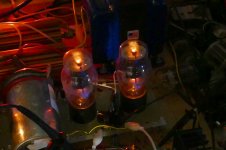
There is a couple pictures of some NOS metal 6V6's happily cranking out 25 watts at 1.125% THD. I didn't push these much beyond the specs since I couldn't see what is happening inside the metal jacket. I put some old glass 6V6 tubes in the test amp, and cranked them up. 31 watts happen at 1% THD.
I mentioned measured power is always input, not output and I explained the difference in an RF example.
Measured power can be input or output in a typical amplifier. It is usually expressed in watts, but there are other valid units.
An RF "transmitting" amplifier, like an audio amplifier takes a small SIGNAL INPUT and amplifies it into a larger OUTPUT SIGNAL that is sent to a speaker or antenna. It consumes electrical POWER INPUT from the power supply to do this. The ratio of OUTPUT POWER applied to the load (speaker or antenna) to POWER INPUT (from the power supply) determines the amplifier's EFFICIENCY. The INPUT POWER consumed by the amplifier and not converted into OUTPUT POWER (input power - output power) is the heat dissipated in the output device (tube or solid state device).
A hypothetical tube amp may consume 10 watts from the power supply, to produce 3 watts of audio. It will then dissipate the other 7 watts as waste heat in the tube. It converts DC power to audio power with an efficiency of 30% which is typical for a good Single Ended amp running at near maximum power output.
....are electrical devices which produce measurable mechanical power and torque at output however electrical power is measured, competently, at input.
A motor is a device which can consume electrical INPUT POWER (usually measured in watts) and convert it into mechanical POWER OUTPUT. It is often measured in HorsePower in the US, but other units are equally valid. Volkswagen often rates their engines in Kilowatts, especially in their European spec cars.....1 HP = 746 watts, they are both valid units for measuring power. So an electric motor that consumes 1 KW input to produce 1 HP output is 74.6% efficient in its conversion. This is lousy for a modern motor.
Electrical power (watts) is a product of the current (amps) and the voltage (volts) in the circuit.
Mechanical power is a product of the torque (ft / lbs in the US) and the RPM divided by a constant (5252 when US units are used).
COMPLETE amplifier measurements whether RF or audio should state the INPUT POWER (from the line or other power source), the available POWER OUTPUT, the gain (how much audio or RF is needed to get the desired or specified audio or RF power at the output), and the distortion characteristics of the amplifier. Different units of measurement and methods are used in the RF world compared to the audio world for distortion, but the principles are the same.
The speaker, or other transducer will convert the electrical power supplied to it by the amplifier into acoustical power. It is a different device with it's own measurement criteria, often not well defined. It is similar to the case of a BLDC motor where an "amplifier" will convert DC power into 3 phase AC power (which could be measured in watts), then apply that power to the mechanical components which will convert that AC power into mechanical rotational power.
6V6 in Class "A" can be rated to as much as 4.5 W
I'm assuming power OUTPUT?
I guess, the maximum continuous power the 6V6 can handle is 4.5Watts input
UH, no.....
The worse case in a class A amplifier is an amp sitting at idle with no SIGNAL input. The volume is turned down, or the record is done playing and the listener has fallen asleep. In this case the tube (assuming a 6V6) is still drawing power from the power supply, according to how it was biased up when the amp was built or set up. The output power is ZERO because there is no music playing. ALL of the INPUT POWER is burned up in the tube (dissipated) as none is being sent to the amplifier's output. The MAXIMUM DISSIPATION of the plate in a 6V6 is 12 watts, and the screen grid is 2 watts, so the INPUT to the 6V6 could be 14 watts without violating any specs. This is not good design practice for reasonable tube life, so less INPUT POWER than the maximum should be applied in a good design.
The GE data sheet gives "typical operation" specs for a SE amp with a 5K load. It shows 250 volts on the plate with 45 mA drawn at zero signal (idle). That is 11.25 watts INPUT POWER to the plate. The screen grid gets 250 volts and draws 4.5 mA for 1.125 watts of INPUT power. The total INPUT POWER is 12.375 watts, and the OUTPUT POWER is ZERO! The tube is turning ALL of it's INPUT POWER into heat.
Now lets apply a simple sine wave and crank it up until the THD reaches 8%. Here the data sheet gives us 4.5 watts of POWER OUTPUT. The tube is now getting 250 volts on the plate but it draws 47 mA for 11.75 watts INPUT. The screen grid gets 250 volts and draws 7 mA for 1.75 watts INPUT. The total INPUT POWER to the tube is 13.5 watts, BUT 4.5 watts of audio power is being delivered to the load, so the tube dissipation GOES DOWN to 9 watts.
Here the efficiency is 33%. 1/3rd of the POWER INPUT to the tube is converted into audio POWER OUTPUT, and the other 2/3 (9 watts) is turned into waste heat in the tube.
In almost all cases with a single ended amplifier, the maximum POWER OUTPUT is limited by how much POWER INPUT can be applied to the tube with no SIGNAL input to the tube. We can do things to improve the efficiency of the tube, like drive the grid positive (A2 operation), but a best case situation is in the 45% range.
A single ended AUDIO amplifier must run in class A, either A1 (no grid current) or A2 (grid driven positive). A2 works well with some tubes, and poorly with others. As stated, it's not often documented in the tube books.
In the RF world an amplifier may run in class A, AB, B or even class C depending on the distortion performance needed in the design. A signal with no amplitude modulation component like FM can run in hard class C where efficiencies can run in the 80+% range, while complex modulation schemes like LTE require near class A linearity.
The situation becomes more complicated when the amplifier runs two devices in a push pull arrangement where the load is shared. Here class A, AB, and near class B operation can be used for audio, with or without grid current.
As with a single ended amplifier, in class A, worse case is at zero signal input. Tube dissipation is maximum when the amp is idling. POWER OUTPUT is still limited by maximum tube dissipation and the calculations are the same as two SE class A amps running at the same time on the same signal.
The other extreme is pure class B. There is NO dissipation at idle, since the tubes are both biased at cutoff. It will peak at maximum UNDISTORTED power output, and drop as the amp is slammed hard into clipping. Pure class B has distortion problems at low signal levels, so we run class AB, where the bias is set somewhere between class A and Class B. Here the point of maximum dissipation will be somewhere between idle and max power output, depending on the bias current.
A competent amplifier designer must test all possible operating conditions and calculate the plate and grid dissipation levels for each. Peak cathode current must be checked for amplifiers operating at high power levels, or when extracting more than the textbook power levels for any given tube. Here computer simulations are valuable time saver, provided the vacuum tube models are reasonably close to the real tube being used.
I can assure you that with the proper circuit, a pair of 6V6's can crank out 30 watts without issue in class AB2.
The 6V6 operate extremely well in AB2, as it's a transmitting valve.
I can find no evidence that the 6V6 was ever INTENDED to be a transmitting tube although it was often used as one (as were many surplus pentodes) once they were in plentiful supply.
(As was the 6L6 originally).
The original metal 6L6 was intended for audio amplifier use. it was the first "high power" pentode created in large volume, so it got used for nearly everything, and several specialized versions of it were created. The original 6L6 pinout had the plate on pin 3 and the heater on pin 2. This created problems with arcing even in audio amps. The 6L6 "guts" were adapted to RF by moving the plate connection to a top cap, and using a base with wider pin spacing to reduce capacitance.....that became the 807.
The 6L6 guts wound up in two different TV sweep tubes. The big one was the 6BG6, with the plate on a top cap. The smaller flavor was the 6BD5GT, yes a 6L6 plate was squished inside the envelope of a tube the size of a 6V6. They were never very popular since the 6AV5GT and 6AU5GT took over the sweep tube duties within a year or two.
A pair of 807s in AB2 have a A-A load of 3k3, and they work perfectly like this, making a LOT of power.
The true 807's are made from 6L6GA guts. There were plenty of "807's" and 1625's made during and after WWII with all sorts of different guts. I have seen some that are missing the RF shielding around the bottom mica, and some with 6L6GC or 7027A guts. These have big wings n the plates and will dissipate 30 watts as compared to the original 19 watt spec.
I put a pair of 6L6GA's to the test with a 3300 ohm load. Somewhere around 120 watts OUTPUT from a pair on 525 volts there will be a tube arc due to ignoring that peak cathode current spec (400 mA for the 6BG6). The pictures show 0.416 %THD at 1 watt and 112.7 watts at 3% THD. It ran there for several minutes, then blew up when I increased the B+ voltage then turned the drive up higher. A second test got the same results...blown 1 ohm cathode resistors.
There is a couple pictures of some NOS metal 6V6's happily cranking out 25 watts at 1.125% THD. I didn't push these much beyond the specs since I couldn't see what is happening inside the metal jacket. I put some old glass 6V6 tubes in the test amp, and cranked them up. 31 watts happen at 1% THD.
Attachments

I can find no evidence that the 6V6 was ever INTENDED to be a transmitting tube
I put a pair of 6L6GA's to the test with a 3300 ohm load. Somewhere around 120 watts OUTPUT from a pair on 525 volts there will be a tube arc due to ignoring that peak cathode current spec (400 mA for the 6BG6). The pictures show 0.416 %THD at 1 watt and 112.7 watts at 3% THD. It ran there for several minutes, then blew up when I increased the B+ voltage then turned the drive up higher.
There is a couple pictures of some NOS metal 6V6's happily cranking out 25 watts at 1.125% THD. I didn't push these much beyond the specs since I couldn't see what is happening inside the metal jacket. I put some old glass 6V6 tubes in the test amp, and cranked them up. 31 watts happen at 1% THD.
You are wrong about the 6V6.
The principle reason it was made with a 0.45A heater (inc the even lower, 12V6 variety) was as a mobile RF transmitter.
The 6V6 was originally purposed as a MOBILE TX valve, running on battery power not for audio.
The rest:-
is exactly what I said, but I did suggest 20-25w was a sensible limit.
TBQH it's pretty suprising considering its dinky little cathode and weeny heater.
I have a pair of 807 amps which run 120W totally reliably hour in, hour out, 24/7.
The HT was 835V.
A-A load was somewhat higher at 5225ohms,- still vastly different in AB2 from anything "normal".
Again, considering the relatively tiny cathode and heater (0.9A) and diminutive anode dimensions, it's quite a feat.
Yes the misleading information which seems to be involving my offerings...will be addressed once and thereafter I'm not interested in going on and on...That's not disrespect, I just have too much 'on'.
I think one of these quotes is from my offerings , maybe two, can't tell. The rest of it, who knows, it became convoluted so I thought ‘once more’…I'm not writing a research paper. There are so many variables with electrically based power output factors that power input is the usual measurement.
That doesn't mean there are no "watts' in output, it means that there are so many variables , several I mentioned that quoting power as 'output' of an amplifier is a generalisation.
If the design maximum input at a particular output is 10W and at that point the amp is 80% efficient one might argue the 'output power' is 8W...and it’s ‘an 8Watt Amplifier’ , but that's just an increment. Unless and to a degree if not using lab quality gear, it’s momentary…even if the input power and signal is at steady state, variables may be happening on the output side may be channging and is it ‘peak’ ‘rms’ ‘average’? See what the label tells you…maybe just ‘P xxwatts’.
If design is done for 'output' watts it has to be within ‘input’ watt specifications and to be realistic has to state the type of transformer and conditions of achieving that power. If direct connection the values of components affecting Z, match voice coil to transformer output and so on and on...
I don't want to go further and deeper ...its pointless and I don’t have the time to argue every possibility on Amplifiers or Transmitters. To wind that part "up". The design factors regarding power are on input, component parameters, ventilation tube characteristics and frequency range. A dirty socket may arise later changing figures or a component variation or a different speaker or a replacement trannie...There are design trade off’s which don’t disappear because of ‘in the limit’ or irrelevant because’…they exist like it or not.
Transmitters are not, other than in fantasy and sales pitch , quoted as power output. One can use an RF power meter on the current going up the stick but again so many factors (including Z and voltage at any rf current point ) arise, it's better to give input power ….which one can usually read on the set label.
When asked what power I am 'running' I give the input power and on any solid state transmitter ‘close enough’ is metered volts across in x amps input.
When an 'amplifier specialist' there's a client tendency to want 'power' noise, bass and distortion... so tell them an output figure of some conjecture and they'll buy it. I won't. On a tube job or hybrid can only make estimate on element current and voltage additions at some point, and that may have little relevance to what is 'escaping' to the 'great void'.
"They" the amplifier gurus can tell the difference of 1 watt (One wrote 4 watts I'm sure it was 5"... they may think so, the expert may think so too .
I can’t.. not with sureness and unless (maybe) its up 3dB on ‘previous’. Wax in your ears, sinus changes and a myriad of other factors come into what you think you hear and the variations in levels.
Some of my comment was approached critically and some seems to be mixed in with others. I hope my explanations are clearer than those disputations.
Thinking on motor drive, as an example. I do recall over 60 years earning 1Hp=746 Watts in the theory of it. Yes some manufacturers use kW and not Hp but on either unit where? at what revs? on what machine? at what ambient? At what fuel consumption?.. on what fuel type and how fresh?...with what ventilation?
Output can affect input, that’s obvious as it loads-up or unloads the power supply but in the normal course, here in Australia and areas where imperal influences still exist we older folk still talk horsepower and ftlbs of torque not only Watts and Newton Metres. I can visualise Hp and Ftlbs far more easily than Watts and NM. My statements in another response are quite accurate irrespective of perceived incorrectness.
When I design a conveyor system or a rotating dome system I want to know how many Hp and what torque to drive it at various loads distances speeds, elevations and conditions. My first motor choice other than environment , space and available voltage and phases is whether it has the capacity to produce the Hp and Torque.
Shaft sizes and so on are of a different aproach. If I go to a motor chart or manufacturer and research ask for a ‘4000 Watt output’ motor or a ‘20watt’ output motor I will be told…'hang on a minute ..tell me about your purpose for it and the loading, cycling, start-up lead, maximum load and so on', even the expected-design conveyor system resistance at best and worst case conditions for a starter. and so on….
Maybe I need 11kV not 415V or 1000V. Motors and amplifiers as just to examples are designed with the POTENTIAL to meet loads and prevailing conditions not to be labelled ‘so many watts/so may Hp’ as a fixed figure. “Hp”/kW classifies the limits of the motor because over that it overheats for one reason or another.
When designing a pumping system I work around available power, costs, volumes, pressures, head and so on and on but one variable often overlooked by clents is the reality of required delivery at actual distance, pipe type and diameter because resistance in friction and fittings impacts on input power.
Put a T in the line or a right angle bend, reduce size, run up to a tank of dam not included in design or just run to another point and you have changed 'outcome desired' which the input is expected to maintain to maintain at or , even reach your desired output at the primary design point. That’s al I have to sayl, spin, nit-pick and speculate away. Nothing I have written is wrong, but I’m not going to get further involved in contesting specious argument.
I'm just reiterating and expanding a little to help any lost sheep. I felt that way too for a minute... Voila.
I don't think you understand what is written rather than I don't understand what is class AB1/AB2 .... What has AB2 as 6V6 as a transmitting valve got to do with anything new. It has been used as an Audio amplifier for at least 60 years.
I explained cycling and power dissipation. That's what it is about...where you bias the applied signal as a tube conduction switch and to what degree if biased '+ve' .
AB1 never runs grids positive, AB2 always has them positive, both are transformer load type tubes and the primary Z has dependence on the secondary being loaded...but again I raise that frequency changes component effects..
The figures for 6V6 are given by manufacturers after exhaustive testing in laboratory not based on overdriving tubes with doubled voltages and the rest of it. I don't subscribe to audiophile fantasies about power performance, manufacturers and tune element colours but I'm ok for audiophiles to pay $40 each for my 12AX7's , they'll soon be on eBay.
The 'good reason' on screen grid voltage I know about...so do the manufacturers that's why its in the 6V6 design specs around certain THD's. We also don't want the screen acting as anode.
You can run any tube to extinction point or high THD however when a curve set shows 500V in push-pull it isn't on each tube continuously...the stipulation is quite clear, 250V-285v maximum. Some might suggest up to 305 volts. A tube can withstand higher voltage for shorter periods of tube conduction and with suitable load dissipate as tubes build up heat, which can be reduced, sometimes only marginally, by a load application. How well does that match?...is a consideration. Running amplifier with no speaker load is not good practice. It's best where a phone jack is used, to use one which includes a resistor taking the place of the speaker/headphones when the jack/RCA connector is withdrawn.
If you want maximum distortion to match the musically-ruined brain of course, exceed the silly old ultra-conservative know-nothing-manufacturer's ultra-conservative, unadventurous, figures. with some amp expert. If you believe that bystander expert then then go for it.
I can get away with driving my ART-13 at 2000v..but why?...what's the point?...As with audio increasing power does not give linear effects of 'loudness'.
On 6V6 or any amplifier tube that manufacturers have to judge are reasonable and competitive outcomes for their tube balanced against longevity fragility, unstable mains voltages and environment. The AB1 never has a grid driven positive and is a tube situation in push pull configuration generally.
An example, not audio but still an amplifier , elsewhere is the Drake R4-C "improvement' changing from 6HS6 to 6Ej7. The tube was no doubt offered to Drake in quantity at better price than the 6HS6. In practice it had more internally generated noise and a shorter life...… you can still buy them for not much however whereas the 6HS6 is scarce by a country mile.
How is my 300B worth even a quarter the cost os a 'matched pair? Matching triodes is perhaps pointless unless both circuits are equivalent. I'm indicating in this meandering there's more to amplification than some tube run down in an audio magazine . The worthwhile approach is to not exceed manufacturers specs and understand how the outcome can be distorted or altered from the manufacturers graphing through being placed in a different component situation and amplifier environment. I've been up since 2 am so I'm getting too tired to continue this ..Voila
AB1 never runs grids positive, AB2 always has them positive, both are transformer load type tubes and the primary Z has dependence on the secondary being loaded...but again I raise that frequency changes component effects..
The 'good reason' on screen grid voltage I know about...so do the manufacturers that's why its in the 6V6 design specs around certain THD's.
We also don't want the screen acting as anode.
the stipulation is quite clear, 250V-285v maximum. Some might suggest up to 305 volts.
On 6V6 or any amplifier tube that manufacturers have to judge are reasonable and competitive outcomes for their tube balanced against longevity fragility, unstable mains voltages and environment.
WHAT on earth is all this rambling on about?
1/ The screen grid IS the anode.
This is well known. The real anode is a "virtual anode" which is exactly why the screen grid acts as it does, and why another 3rd element has to be inserted to inhibit secondary emission.
It's exactly the reason why the main gain changing element in valves is the potential of the screen, its alignment and why high screen currents cause losses in efficiency.
2/ "the primary Z has dependence on the secondary being loaded"
. well NO, the A-A loading is the main interraction between the internal impedance of the device.
Driving it in AB2 - the g1 positive has a drastic effect on the internal gain and impedance of the device, doubling its current conducting capabilities, hence why you use half the A-A impedance in AB2 to get double the power.
3/ Running 6V6 at 250-285V? This is craziness.
I have an ancient Bogen amp from the mid 50s.
It is one of the best, sweetest sounding 6V6 amps ever made, no contest.
The HT is 365V, which of course with cathode bias means it's running about 345V across the valve.
I measured it, because suprised by the frequency response & THD claims.
Guess what it makes about 10W clean (once sorted out) and yes the frequency response IS as flat as claimed from 25hz-25khz, yes the distortion is as low as claimed, and yes 60yrs later it's still running absolutely fine with valves 50yrs old.
I get the feeling, contributing to such debate is an oxymoron.
All you need is a few old amplifiers, some test equipment, look what they did, and stop trying to reinvent the wheel. 🙄
I do appreciate the input of Tubelab_com
It's actually quite suprising to see, (if I could be bothered), it's possible to hammer out quite easily a nice clean 40+W from a PPP quad of the little 6BW6 with really low distortion.
I will have to try some day.
Last edited:
Hi...thank you for your contribution and particularly the dissertation on the realities of the vacuum tube. If only the tube manufacturers had been able to realise what you have...discovered.. they could have saved on all those anodes. The output transformer could then have gone fromG1 to G2 in your old Bogan Amp..
I have so many responses to my 6V6 observations that I might forget to revisit you. I'm a great believer in mnemonics and I will remember 6volt heater 12 volt tube, Bogen and Oxymoron using Control'F' to get back with my multilinguistic Rosetta stone and examine your explanations more closely. Meanwhile as said earlier. I'm just too busy at present for spuriousness. Keep that filament warm. My regards
I have so many responses to my 6V6 observations that I might forget to revisit you. I'm a great believer in mnemonics and I will remember 6volt heater 12 volt tube, Bogen and Oxymoron using Control'F' to get back with my multilinguistic Rosetta stone and examine your explanations more closely. Meanwhile as said earlier. I'm just too busy at present for spuriousness. Keep that filament warm. My regards
You know you are only ignorant once.Hi...thank you for your contribution and particularly the dissertation on the realities of the vacuum tube. If only the tube manufacturers had been able to realise what you have...discovered.. they could have saved on all those anodes. The output transformer could then have gone fromG1 to G2 in your old Bogan Amp..
(spelt Bogen, thanks to David Bogen a Jewish emigre from Europe who realised a large market was to be had making PA equipment. The company exists today.)
Being ignorant and willingly stupid are not so forgiveable.
There is loads of literature out there, so read it, and stop trying to diss people who may have contributions to save you getting embarrassed in public.
here it is in black and white from RCA in 1937:-
oestex does have an excellent site about valves.The most important attribute of the Screen-Grid - but one that is not clearly explained in Tube Manuals - is that it becomes the primary ANODE in the tube - ie when the Screen-Grid is energised to a positive potential to the Cathode, the Plate becomes simply a passive collector of those electrons emitted from the directly or indirectly heated Cathode that have been attracted by, and passed through, the Screen-Grid to it.
The RCA 1937 Receiving Tube Manual tells us this way at Page 9:
"The Screen is operated at a positive voltage and, therefore, attracts electrons from the Cathode. But because of the comparatively large space between the wires of the Screen, most of the electrons drawn to the Screen pass through it to the Plate. Hence the Screen acts as an electrostatic force pulling electrons from the Cathode to the Plate."
Thus when a Screen-Grid is present, IT is the ANODE and the Plate becomes a secondary or pseudo-anode only.
Understanding this fundamental design feature is crucial to understanding the significance of maximum Screen Grid rated voltages and their relationship to Plate voltages in all cases for (strapped) triode, tetrode, pentode, beam power tube or ultra-linear configurations.
May I suggest you read it before posting anything else? 🙄
Debate-Oxymoron, seems I wasn't far wrong.

Last edited:
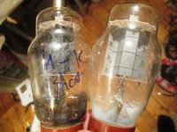
For those interested, I have one in my junk pile.The true 807's are made from 6L6GA guts. There were plenty of "807's" and 1625's made during and after WWII with all sorts of different guts.
I have seen some that are missing the RF shielding around the bottom mica, and some with 6L6GC or 7027A guts. These have big wings n the plates and will dissipate 30 watts as compared to the original 19 watt spec.
I really struggled to find this unusual 807, & it went pop when I tried to remove a seized TC.
The one next to it was a DOA 807 which appeared to have an internal short.
You can clearly see the big difference in anode dims.
I don't think a photo of these 2 types exists.
In my experience the "grey plate" 807 seems to red plate easier and more unevenly than the dull metal ones.
Sadly I couldn't test the BIG anode one, but the French Thomson 5933W in Europe was a much more rugged beast, again with lots of variants. (below)
I did note the great variety of different constructions, and the large production spreads, as wide as 35% qc at identical parameters.
It sure makes it a tough job to select out valves from a big pile, - this applying clearly to 6V6 too, which also has an aligned screen.
Attachments
Last edited:
The true 807's are made from 6L6GA guts.
I started out making amps, mostly for guitar, out of parts salvaged from discarded TV's, radios and HiFi sets in the early 1960's. That continued through my teens. At age 20 I got a job at a local Motorola plant, where silicon was free just for filling out a sample request form, so my amps were mostly sand based life forms for about 20 years. As the years went by I still made amps from both silicon and vacuum tubes. Motorola had sent me to college twice for engineering degrees at their expense, and for the last 25 years of my 41 year career, I was a transmitter design engineer.
Transmitters are not, other than in fantasy and sales pitch , quoted as power output.
I assure you that every transmitter licensed for use in the USA and most of the rest of the world MUST be specified in RF power output as measured with a direct power meter connection to a 50 ohm load, just as an audio amp is measured with a power meter into an 8 ohm or other specified load).
A waiver of the direct connection requirement for cellular phone was being studied when I left the phone group around year 2000. Any "permanent" installation licensed by the FCC for use in the USA must ALSO quote its EIRP power rating. Effective Isotropic Radiated Power is the specified 50 ohm power from the OUTPUT of the transmitter MINUS the feedline losses (cable to the antenna) PLUS the antenna gain. Antenna gain is the apparent boost in signal gained by focusing it's signal in one plane or direction rather than sending it out in all directions like our sun does. Some "permanent installations" like a TV station will have a maximum EIRP spec, and must also state their measured 50 ohm power at the transmitter. A US spec DTV station must run a maximum EIRP of 1 Megawatt. This is usually accomplished with transmitter RF power rating of about 10 KW and 20 dB of antenna gain / feedline loss.
Older amateur and citizens band radio power requirements were stated in "DC power input to the final RF amplifier" because many hams did not have accurate RF power measurement capability. Those regulations were eliminated many years ago in the USA in favor of direct RF power measurement at the transmitter output connector.
The true 807's are made from 6L6GA guts
Sometime around year 1995 I got a call from an old friend who is a surplus dealer. He got a call from some people who had been demolishing an old abandoned warehouse complex when mercury was discovered and the operation was halted. He bought the contents cheap and offered me ALL of the tubes for FREE if I would come and help move all the contents to a storage facility. The building had been condemned years previously, and had been subject to vandalism and vagrant living quarters, so It was trashed.
I would up with over 100,000 loose vacuum tubes randomly stored in boxes, 55 gallon drums, and paper bags...AFTER tossing the obvious broken tubes into the trash prior to moving them. All of this stuff had been collected during the 1950's and 1960's and consisted of TONS of military spare parts and assemblies from WWII and the Korean war era. They tubes had been pulled and sorted in paper bags, all of which had rotted or been eaten my rats and roaches.
I spent over 5 years sorting through it all. I would say that I had at least 1000 807's and 1625's, and probably 3/4 of them were junk, broken, or had mangled pins. I saw so many different "things" called 807 that I lost track. I did have some of the 5933 flavor.
You are wrong about the 6V6.
There were very few 6V6 types in the military spares collection. The ones I had were VT107 variants.
According to the data in the Motorola Museum the 6V6G was designed by Ken Rad specifically for use in car radios, including car police radios. In the 1930's and 1940's cars had a 6 volt electrical system and people often used the radio when the car was not running, hence the 450 mA heater. The entire tube was optimized for low power operation. Automobile police radios in the 1930's did not transmit, they could only receive. Mobile transmitters were not yet common when the 6V6 was introduced in the mid 1930's. I'm sure that some 6V6 tubes were used as RF output devices, but the bigger, more powerful 6L6 was available by the time that two way to the car transmission was common (first introduced in 1939, same year as the metal 6L6).
https://www.landley.net/history/mirror/6800_MotDoc.pdf
Regardless, it is a pointless waste of time to debate the origins of a nearly 90 year old vacuum tube when what is made today bears virtually no resemblance to the 6V6's of old. They are designed to work in guitar ampw at voltages far beyond what's on the data sheets.
It's actually quite suprising to see, (if I could be bothered), it's possible to hammer out quite easily a nice clean 40+W from a PPP quad of the little 6BW6 with really low distortion.
There are a lot of tubes that can crank out far more power than was expected from them when they were originally designed. Extensive testing and experience has led to some of these discoveries. Many tubes lead multiple lives under different type numbers. You figure this out by cracking several open and examining their guts, then comparing the published curves....
For example, any old timer here knows the 50L6 tube. It was the workhorse audio output tube in the octal version of the AA5 vacuum tube AM radio. It exists in three different heater variants, the 12L6, the 25L6 and the 50L6. The 35L6 is NOT the same tube. Why is there no 6 volt flavor? There is. The type number 6L6 was already used, so the 6 volt flavor is the 6W6, which also has different heater variants. There are several variants in different bottles too. The 6GC5 is a 6W6 in a fat 9 pin bottle, and there are other flavors too, but i can't remember all the numbers now. The tiny 50C5 and 50B5 tubes are very similar 7 pin tubes, but have much smaller plates so can't be pushed as hard.
So if a 50L6 can handle 200 volts maximum on it's plate, but a 6W6 can eat 300 how much can the tube really eat? The 6W6 has a "peak positive plate voltage" spec of 1500 volts in TV sweep duty, so the plate VOLTAGE is not a problem. Continuous AVERAGE plate dissipation is the limiting factor. If you keep increasing the plate voltage, you must reduce the plate current to keep the dissipation in check. At some point the idle current will be too low to eliminate crossover distortion.
Last night I discussed plate efficiency. Any amplifier tube or solid state will generate wast heat. The more efficient an amplifier is, the more power you can get out of it, because less of it's input power is converted to heat.....we improve the efficiency, and we boost the power output capabilities of the amp. I stated last night that using AB2, driving the grid positive, is one way to improve efficiency. Choosing the right tube is even more effective.
Lets just say that we need a 100 mA peak current through a tube for a certain power output. If we drive the grid to 0 volts, the plate curves show us that we will drop about 80 volts across a 6V6, which needs 250 volts on its screen to get there. Swapping our 6V6 for a 6W6 will reveal that a 6W6 can pull 100 mA through it's plate with only 40 volts across the tube, and if only needs 110 volts on its screen to get there. In this case tube choice, and the associated circuit design changes can cut out losses in the vacuum tube in HALF.....of course, there are penalties. As I stated earlier the 6V6 was designed and optimized for overall efficiency. it has a 450 mA heater and a tiny cathode. The 6W6 has a big fat cathode and a 1.2 Amp heater to create a much bigger space charge cloud.
I started out making amps, mostly for guitar, out of parts salvaged from discarded TV's, radios and HiFi sets in the early 1960's. That continued through my teens. ...
As I stated earlier the 6V6 was designed and optimized for overall efficiency. it has a 450 mA heater and a tiny cathode. The 6W6 has a big fat cathode and a 1.2 Amp heater to create a much bigger space charge cloud.
All good stuff, I watch what you have been up to with great interest and a twinge of envy. I used to do this as a teenager too, making amps to shake the roofs of school mates houses on guitar duty, with hints from my Dad.
We made a whopping bass reflex, with I think it was FANE speakers, - that was LOUD!
(I just made another pair something similar this summer, and it's fantastic).
Over the other side of the pond things are not quite the same...
Having said that, we did have GEC, STC, Brimar & Mullard, which did churn out some excellent stuff, as well as French Thomson CSF+some interesting German & Italian gear.
I have to agree about cathode ratings.
The first thing I always look at is the size of heater.
If for its size it has a whopping heater, then there's a very strong chance it has an outsize cathode in there.
One of my mil spec valves is scarcely bigger than a little finger, yet it has an anode rated quite low Anode diss, but a heater nearly as powerful as the 6L6.
Most of the docs rate it bumbling along at 165V or so, so it's clearly a high gain low impedance device, then you start looking in the industrial spec docs for it, and find out it's quite ok running the anode at 500V, as it's listed for Voltage stabiliser duty.
I first tried running them cathode biased, which gave some idea what they might do,- was a bit underwhelmed so went to fixed bias quite quick from there.
So, a bit like you, I whopped it up to 500V, wound the screen to a nice steady 300, pushed back the bias right back to -32V, and hey presto, some fantastic bit of kit.
It doesn't red plate, doesn't run away, but you have to put chokes/resistors in the anodes as soon as they are in PPP, or you get wild oscillation.
After discovering they work perfectly in PPP, (so as a quad), I then had to hammer the daylights out of them to see what they could do...err, yes at 0v on the g1 they conduct 1/4 of an amp... WOW!
I originally used large gas stabilisers on the screens at 300V, pushing them to the max (40m/a). To my astonishment I saw the stabiliser valves extinguising on peaks.
I notice you have done similar things.
This meant the screen grids were taking large hamburger size slodges of current, so that entailed making a proper stabilised supply a 300V.
After looking at it carefully, they were taking more than 50m/a screen current, that's 15W!~ (and only rated at about 6!)
Another WOW! I only ever saw insane currents like this with the 8417.
(which of course were never sold in Europe).
I see they only survive because these currents are only on short lived peaks, with the other half cycle switched completely off..
It turned out these little beasts behave like ultra miniature KT88s..(have same gain/conduct as much current!),.and no suprise at all to see the heater requirement from the tiny quad as being more than 2.5A, so that's the heater of one KT66/KT8 in a pair of the little jiggers.
Pushing them to the limit, they churn out 50W with minimal distortion, taking the space of barely a large box of matches.
In fact 4 of them will fit inside a box of matches...
I reckon some of the stuff churned out in the late 50s-early 70s was the BIZ, but few people have heard of some of the rather more exotic stuff, lurking in corners collecting dust and costing peanuts.
Last edited:
You are wrong about the 6V6.
The principle reason it was made with a 0.45A heater (inc the even lower, 12V6 variety) was as a mobile RF transmitter.
The 6V6 was originally purposed as a MOBILE TX valve, running on battery power not for audio....
All I have read makes me think the 6V6 is a "big/thrifty" 6F6 and a "small" 6L6, both aimed at AUDIO (though used for everything).
The 6L6 is too big for home or car radios. Home radios were a big thing but when 6V6 was born CAR Radios seemed to be the next big thing. The 6F6 was a good upgrade from '50, but needed large grid drive, and near as much heater power as a 6L6 for far less output Power. Someone (I don't think it was RCA) did a mix-n-match of the two others to get a low-cost, small-drive, thrifty heater tube good for 3-5W SE 10-14W p-p. It quickly drove-out 6F6 in home and car radios.
> 'watts' is an' input' term not an output term.
I think what he is saying: we can "offer" 5W to the speaker. If the signal is at bass resonance, Z about 5X the nominal, it will only take 1 of those 5 Watts. The speaker may still be "flat" because its electro-acoustic efficiency rises at resonance. This was known and accepted by all the Old Time Designers (see RDH 3rd).
Attachments
Last edited:
The 6V6 was the "cheapy" amp used in loads of table top radios, usually SE, and usually sounding muffled, distorted and pretty terrible. It replaced the AC-PEN type 4V valves used in most of Europe before.
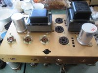
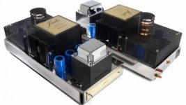
I have given up testing other people's amps in Hi end shops for fear of blowing them up. Here was the little jewel I got for about 100USD, brand new in a box,- never finished.
The brand new caps were already DOA, the 2, 6V6 were also duds, so not much work to make a brand new amp really.
The OPT is selectron, and now I know, has superb frequency response, nice linear waveforms, looks nondescript (Audiophile people of course look down their noses at it!), and doesn't weigh very much*.
I think it uses about 50W all in.
My spare rebuilt one I used for testing, cost me about 10EURO in all to rebuild & I didn't even match the 50yr old, good s/h OPVs. I never saw one tested, so I did all that, and although it fell 2-3W short of spec, I use it for fun to embarrass modern "hi end" stuff.
*I think it weighs about 5-8kg, easy to carry in one hand.
I checked out my nicely rebuilt and modded one against an all singing all dancing Unison research thingy costing 4000USD, supposed to use 300W....
Lower trace that amp, upper trace the 4000USD thing with violent inbalance/distortion.
Says it all really
As you can see even approaching 7-8W it's already way out of kilter.
No wonder it sounds bad.
What does the PR say?
[FONT=Arial, Helvetica, sans-serif]
[/FONT]
and another load of crap!! 😀
[/FONT]
[FONT=Arial, Helvetica, sans-serif]
[/FONT] [FONT=Arial, Helvetica, sans-serif]Yea right it can't even produce linearly 1/4 of that!
I wonder what they did in their painstaking design & testing?
What are they all smoking?
So what do I prefer? A 60yr old classic pair of monoblocs with 6V6 at 200-250USD or some overhyped Italian junk at 20x the price?
There's another French SE amp from Jadis in the same room complete with whopping 845 and simply giant size transformers.
[/FONT][FONT=Arial, Helvetica, sans-serif]Weight 35kg EACH!
The shop owner begged me not to test it, just in case that 20W max, underpowered pile of dirty sounding rubbish turned out to be just as bad (which I suspect it is!).
[/FONT]
[FONT=Arial, Helvetica, sans-serif]
[/FONT]
[FONT=Arial, Helvetica, sans-serif]
I think George did easy better breadboarding a couple of 6V6 in Ab2 with 1% distortion eh, and probably cost all of 200USD all in?
[/FONT]
I have given up testing other people's amps in Hi end shops for fear of blowing them up. Here was the little jewel I got for about 100USD, brand new in a box,- never finished.
The brand new caps were already DOA, the 2, 6V6 were also duds, so not much work to make a brand new amp really.
The OPT is selectron, and now I know, has superb frequency response, nice linear waveforms, looks nondescript (Audiophile people of course look down their noses at it!), and doesn't weigh very much*.
I think it uses about 50W all in.
My spare rebuilt one I used for testing, cost me about 10EURO in all to rebuild & I didn't even match the 50yr old, good s/h OPVs. I never saw one tested, so I did all that, and although it fell 2-3W short of spec, I use it for fun to embarrass modern "hi end" stuff.
*I think it weighs about 5-8kg, easy to carry in one hand.
I checked out my nicely rebuilt and modded one against an all singing all dancing Unison research thingy costing 4000USD, supposed to use 300W....
Lower trace that amp, upper trace the 4000USD thing with violent inbalance/distortion.
Says it all really
As you can see even approaching 7-8W it's already way out of kilter.
No wonder it sounds bad.
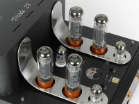
What does the PR say?
[FONT=Arial, Helvetica, sans-serif]
andA pair of EL34 power tubes per side provide 22 wpc in Triode mode and 45 wpc in Ultralinear mode. An elegant, refined amp with power from Italy. $3995 retail
[/FONT]
[FONT=Arial, Helvetica, sans-serif]To ensure high quality sound in an amplifier with a push-pull configuration, however, it is essential that all individual amplification stages, especially the two semi-output amplifiers, are carefully designed and constructed to prevent the formation of dangerous and compromising odd-order harmonic distortion. This is even truer for the output transformer.
The new Triode amplifier 25 has experienced a long and painstaking design and testing period ..
and another load of crap!! 😀
[/FONT]
[FONT=Arial, Helvetica, sans-serif]
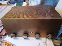
[/FONT]At first glance this amplifier looks positively handsome. The sample supplied for review sported a real Cherry wood fascia which I found rather attractive.....
[FONT=Arial, Helvetica, sans-serif] 😱[FONT=Arial, Helvetica, sans-serif]Research really have got the recipe right with this amplifier as it sounds sublime to me and I could sit here and probably type a hundred superlatives and you would probably read it in disbelief, .... [/FONT]it was apparent just how lucid and insightful this amplifier really is
[/FONT] [FONT=Arial, Helvetica, sans-serif]Yea right it can't even produce linearly 1/4 of that!
I wonder what they did in their painstaking design & testing?
What are they all smoking?
So what do I prefer? A 60yr old classic pair of monoblocs with 6V6 at 200-250USD or some overhyped Italian junk at 20x the price?
There's another French SE amp from Jadis in the same room complete with whopping 845 and simply giant size transformers.
[/FONT][FONT=Arial, Helvetica, sans-serif]Weight 35kg EACH!
The shop owner begged me not to test it, just in case that 20W max, underpowered pile of dirty sounding rubbish turned out to be just as bad (which I suspect it is!).
[/FONT]
[FONT=Arial, Helvetica, sans-serif]
hyped again..These amplifiers bring an immense crushing breadth, a grandiose sound image which extends way beyond the bounds of the speakers and even of the listening room..."
[/FONT]
[FONT=Arial, Helvetica, sans-serif]
yea right!When we last visited France we heard those those mono amps, which sounded so good that we are certain they represent without a doubt the very top of this application.
I think George did easy better breadboarding a couple of 6V6 in Ab2 with 1% distortion eh, and probably cost all of 200USD all in?
[/FONT]
Attachments
Last edited:
What if all you wanted was say, 100mW?
A triode wired 6V6 in SE sounds the closest to a 45 in SE that I have found. If you like the SE tube amp sound, need low power without the expense of a DHT, then a triode wired 6V6 is a good choice. I ran mine at about 320 volts and 25 mA or so and used a cheap Edcor XSE OPT that was 5K to 8 ohms. I loaded the OPT with a 20 ohm resistor and wired my 32 ohm headphones directly across that resistor for a 12.3 ohm load resulting in the tube seeing about 7700 ohms.
Under those conditions the cheap Edcor is flat from below 20 Hz to beyond 40 KHz.
I liked the 45 DHT better as a headphone amp, but the 6V6 version is around here somewhere, still in a box from a move 5 years ago.
Home radios were a big thing but when 6V6 was born CAR Radios seemed to be the next big thing.
My first car was a 1949 Plymouth. The Motorola built AM radio in that thing ran a PAIR of 6V6's in push pull fed by a vibrator power supply. The car's electrical system was 6 volts, so I as a zero budget high school kid had no easy way of sticking the requisite 8 track deck under the dash feeding the usual 6X9's in the package tray......so I junkyard shopped a second stock AM radio for my car. It had the power supply and audio amp on a separate chassis from the tuner, so I ripped off the two amps, mounted them to a pine board and stuck them in the trunk, feeding the required 6X9 speakers. They were fed from my Panasonic portable cassette player. Suddenly, I had the "baddest" car stereo system in high school.....remember to a 17 year old kid LOUD = good.
Last edited:
> 1949 Plymouth. The Motorola built AM radio in that thing ran a PAIR of 6V6's
That's the fancy radio. My brother's unmolested (bought from a dead farmer who owned it from new) '41 Plymouth had one "6V6" (IIRC the Loctal version) for maybe 3 Watts output. IIRC it was a Mopar captive-brand. It had a really hot 6.5" speaker in the dash. I never looked to see if it had 6x9 holes in the shelf. The radio didn't work and repair was not trivial. He ran a battery boom-box on the seat.
That's the fancy radio. My brother's unmolested (bought from a dead farmer who owned it from new) '41 Plymouth had one "6V6" (IIRC the Loctal version) for maybe 3 Watts output. IIRC it was a Mopar captive-brand. It had a really hot 6.5" speaker in the dash. I never looked to see if it had 6x9 holes in the shelf. The radio didn't work and repair was not trivial. He ran a battery boom-box on the seat.
At least in 1949, there was the Plymouth, the Plymouth Special, and the Plymouth Special Deluxe. My grandfather bought the Special Deluxe brand new in early 1949. After he had passed my grandmother kept getting into "incidents" where she would roll backwards into the car behind her on the Georgia hills, so the court told her, automatic trans or no drivers license. She bought a brand new 1970 Valiant and I got the '49. I finally traded it for a tube stereo around 1990.
If memory serves correctly the radio had an oval speaker, but I do not remember the size. It was Mopar branded, but Motorola made, as were a lot of the OEM radios in the 40's.
Motorola made the radios and alternators for Chrysler well into the 70's, then did the engine controllers until Chrysler started making their own in the 90's. Lets just say that the right passwords and some serious searching got me the internal design documents for the 1984 turbo engine controls. That's one of the reasons that my turbo Dodge went faster than everyone else's…..and I had some magic parts made by a guy named Shelby.
My Plymouth did not come with 6 X 9 holes, but I fixed that with a jig saw.
Once I got a job at Olson's Electronics, I stuck a 12 volt alternator and battery in the car and Mr. Jig Saw made some 5 inch round holes in the forward kick panels too. I had a Craig Pioneer Quadraphonic 8 track player in the car for a few years.
If memory serves correctly the radio had an oval speaker, but I do not remember the size. It was Mopar branded, but Motorola made, as were a lot of the OEM radios in the 40's.
Motorola made the radios and alternators for Chrysler well into the 70's, then did the engine controllers until Chrysler started making their own in the 90's. Lets just say that the right passwords and some serious searching got me the internal design documents for the 1984 turbo engine controls. That's one of the reasons that my turbo Dodge went faster than everyone else's…..and I had some magic parts made by a guy named Shelby.
I never looked to see if it had 6x9 holes in the shelf.
My Plymouth did not come with 6 X 9 holes, but I fixed that with a jig saw.
Once I got a job at Olson's Electronics, I stuck a 12 volt alternator and battery in the car and Mr. Jig Saw made some 5 inch round holes in the forward kick panels too. I had a Craig Pioneer Quadraphonic 8 track player in the car for a few years.
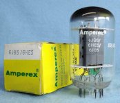
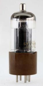
Yes it's a 6V6 with double the size heater.
I decided to give those a miss.
As with so many of the 12 pin US made valves, there are lots of different variants, and sorting out which is the right one from "Sylv, RCA, Zenith, National, GE," etc
Apparently the docs give it a 12W Pa, but Sylvania 19.
I decided to give those a miss.
As with so many of the 12 pin US made valves, there are lots of different variants, and sorting out which is the right one from "Sylv, RCA, Zenith, National, GE," etc
Apparently the docs give it a 12W Pa, but Sylvania 19.
The tube in your picture caries three type numbers as do most of mine, 6JC5/6JB5/6HE5.
GE's own literature states that the 6HE5 is a compactron version of the 6EZ5, which was on the dollar list until it got mentioned here, then poof all of them were gone, off to Asia. They were sort of a hybrid between the 6V6 and the 6W6 and worked very well in a SE amp.
GE's own literature states that the 6HE5 is a compactron version of the 6EZ5, which was on the dollar list until it got mentioned here, then poof all of them were gone, off to Asia. They were sort of a hybrid between the 6V6 and the 6W6 and worked very well in a SE amp.
- Home
- Amplifiers
- Tubes / Valves
- 6V6 Output?